In this chapter, we will discuss Network topology. A network topology is a physical connection or the physical orientation of the devices in a network.
A network topology defines how exactly the computers, printers, network devices, and other devices connect to a network. In other words, a network topology describes the layout, physical orientation of the cables and devices as well as the path used by the data transmissions. The topology influences the functioning of the network to a great extent.
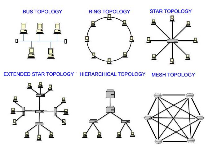
Networks can have both a physical and a logical topology. Physical topology refers to the physical layout of the devices and transmission media. Commonly used physical topologies in a data network are:
- Bus Topology
- Ring Topology
- Star Topology
- Extended Star Topology
- Hierarchical Topology
- Mesh Topology
Besides Physical typologies as listed above, logical topology defines how the medium is accessed by the hosts for sending data besides the physical connectivity.
Factors determining the choice of Toplogy
There are several factors which decides the choice of topology.
- Cost
- Scalability
- Bandwidth Capacity
- Ease of Installation
- Ease of fault finding and maintenance
The different types of physical topologies are explained here:
Bus Topology
A bus topology is commonly called a linear bus, that connects all the devices using a single cable. This backbone cable or the bus proceeds from one computer to the next like a bus line going through a city.
With a physical bus topology, the main cable segment must end with a terminator that absorbs the signal when it reaches the end of the line or wire. If there is no terminator, the electrical signal flowing through the cable representing the data bounces back at the end of the wire, causing errors in the network. This is somewhat like matching RF cables to the antenna.
Bus Topology is the original form of Ethernet (IEEE 802.3). It used 10 Base5 (Thicknet) as backbone and 10Base2 (Thinnet) as LAN distribution. It is limited by the Ethernet 5-4-3 rule where you may have a maximum of 5 segments with 4 repeaters and 3 mixing segments. This limitation applies to both Thinnet and Thicknet. The number of nodes can be 30 in thinnet and 100 in thicknet per segment. Segment length is 185 Mtr (Roughly 200, hence -2 in 10 Base2, where 10 is bandwidth in Mbps, Base stands or Baseband signal and 2- for 200 Mtr segment length). Similarly, 10Base5 is functions up to 500 Mtr as segment length.
Advantages :
- Uses less cable, so inexpensive
- Easy to add stations
- Reasonably good for small network
Disadvantages:
- No longer used.
- If the backbone breaks, whole network crashes.
- Limitation on number of devices
- Fault finding is difficult
- Whole traffic from single backbone, hence chance of congestion
Ring Topology
Like the start and Bus topology. the logical ring is another important topology in LAN connectivity. As the name implies, hosts are connected circularly like a ring. Unlike the physical bus topology, the ring topology does not need to be terminated at the beginning and the end, since it has no beginning or end.
Data is transmitted in a way, unlike the logical bus topology. A-frame travels along the ring, which stops at each node. If a node wants to transmit data, it loads its data as well as the destination address to the frame. The frame then continuously revolves around the ring until it finds the destination node, which takes the data out of the frame. The advantage of using this type of method is that there is no chance of collisions of data packets.
- All devices have equal priority for access to media.
- The ring may be single or double.- Unidirectional and bidirectional. The later one has the redundancy. Each ring works independently, but if one ring fails, it will work like a single ring.
- A node can be added without interfering with the network.
- Data packets travel at great speed as compared to the bus.
- No collisions
- Easier to fault find
- No terminators required
- Used in SONET (Synchronous Optical NETwork), SDH (Synchronous Digital Hierarchy) network.
Disadvantages:
- Requires more cable than a bus and the connecting hardware is costly.
- A break in the ring or node shut down will bring the whole network down.
- Slower than Star topology.
Hierarchical Topology
A hierarchical topology is just like an extended-star topology. The primary difference is that it does not use a central node like the star. Instead, it uses a trunk node from which it branches to other remote nodes.
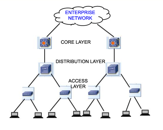
Also known as the tree Topology, it may be a Binary Tree or a backbone tree. This topology looks like as extended Star topology and serves somewhat like bus topology.
This topology looks like as extended Star topology and serves somewhat like bus topology. Typical example is Hierarchical Internetworking Model used in Enterprise Network. The switches are designated as the core layer, distribution layer and the access layer.
Mesh Topology
This is a topology in which devices are connected with many alternative interconnections between network nodes. In a true mesh topology, every node has a connection to every other node directly as well as indirectly to meet any unexpected failover approach. The full-mesh topology connects all devices (nodes) to each other for redundancy and fault tolerance, implementing a full-mesh topology is expensive and difficult. The full-mesh topology usually implemented in WANs between core routing devices.
Some features of the mesh topology is as follows:-
- Not common on LANs.
- Most often used in WANs to interconnect LANs.
- Each node connects to every single node for redundancy.
- If a few links break, the packets will follow other available paths.
- It is “Fault-Tolerant” since redundant paths are there.
- Expensive, difficult to install and manage.
Logical Toplogy
A network’s logical topology is how the hosts communicate across the medium. The broadcast and token passing are the two most common types of logical topology.In broadcast topology, each host addresses its data for a particular NIC to a multicast address or a broadcast address on the network medium. The stations need not followany order to use the network, as its first-come-first-serve. Ethernet also works this way.
The second logical topology is token passing. Token passing regulates the network access to the host by passing an electronic token sequentially to each of them. A host can only send the data on the network, when it possess the token. If the host has no data to send, it let the token pass to the next host, and the process repeats itself. Two examples of networks that use token passing are Token Ring and FDDI, both of which are examples of token passing on a physical ring topology.
Take a Quiz of this topic :