
In my last blog, I have explained the spanning tree protocol (STP) extensively. Let us now discuss the Different types of Spanning Tree Protocol in detail. In this article, I will cover the different types of STP and explain each of them in detail. The first one among the different types of Spanning Tree Protocol, i.e., the original STP, is already discussed in the hyperlinked chapter.
Different types of Spanning Tree Protocol
1. The original STP (802.1D)
It is also referred to as the Common STP, standardized as 802.1D. This standard considers only one instance of spanning tree for the entire layer-2 network irrespective of the number of VLANs. It will have only one spanning tree for all VLANs. As discussed earlier in the article Spanning tree protocol, you may have figured out that this standard is pretty much similar to the RIP in layer-3. Like it sends the hello BPDU, it has something like hold time (Max_age), etc. The default time for hello BPDU is 2 sec configurable in 1 to 10 Sec. The forward delay has the default time 15 sec; similarly, the max_age is 20 sec by default.
The main disadvantage of the original STP is the convergence time it takes for the network to converge. By default, the time is 50 sec for any port to go from the blocking state to the forwarding state. As an old standard, the time was reasonable in the early days of networking. In the current scenario, a network cannot afford the delay of 50 sec for a port to converge.
For a complete study of the original STP, refer to this article Spanning tree protocol.
2. Per VLAN spanning tree (PVST) and PVST+
It is the advancement or the modification by Cisco to the 802.1d standard. It can have a dedicated instance of spanning tree for each VLAN. If a network has 10 VLANs, then each VLAN may have a different Root Bridge and the spanning trees. The timers and convergence time is the same as that of the original STP. As a native Cisco standard, PVST functions with the ISL ( Inter-Switch Link) trunks only; and doesn’t support the 802.1q trunks.
It can be configured for VLAN trunks to forward some VLANs and block others. Per VLAN spanning tree is able to load balance by allowing some VLANs on one trunk link, while other VLANs on the others.
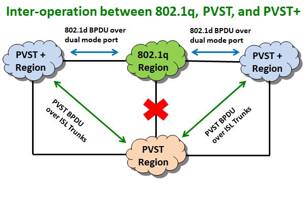
PVST+
PVST+ is an extension of PVST to allow Cisco devices to inter-operate with the 802.1Q trunks. It permits communication between an 802.1Q region with a PVST region by mediating between them. An IEEE 802.1Q region cannot communicate directly with a PVST region but does with a PVST+ link between them.
It helps to tunnel the PVST BPDU on an 802.1Q region as shown in the figure below.
3. Rapid Spanning Tree Protocol (RSTP)
The RSTP, IEEE802.1w, is the new evolution of the original 802.1D standard. It basically addresses the convergence and timer issues of the original STP, while keeping the other parameters almost the same. The 802.1w is backward compatible with the legacy STP.
The RSTP modified the port-state of the original STP from five status to three. The table below shows the comparison of the port status in both the standards:
| 802.1D port state | 802.1w port state | Port inclusion in the active topology | Port inclusion in the active topology |
|---|---|---|---|
| Disabled | Discarding | No | No |
| Blocking | Discarding | No | No |
| Listening | Discarding | Yes | No |
| Learning | Learning | Yes | Yes |
| Forwarding | Forwarding | Yes | Yes |
Port Roles
In contrast to the original STP, the port roles of the root port and the designated ports are the same. Whereas, the blocking port is divided into two categories: The alternate port and the backup port.
For the description of the root port and the designated port, please refer to the article Spanning Tree Protocol.
Alternate and back up ports relate to the blocking port of 802.1D. The function of the alternate port and backup port is as shown in the figure below:
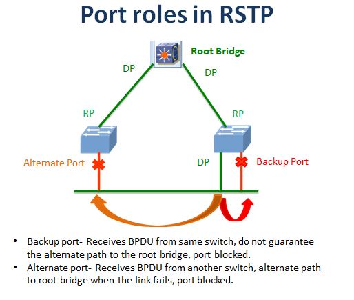
As shown in the above figure, the alternate port receives BPDU from another switch. In case of failure of the root port link, the alternate port will provide the redundant path. This port is blocked in RSTP, but it replaces the root port in case of failure.
The backup port receives the BPDU from the same switch. It is a redundant connection to the same segment and takes over if the designated port fails. The difference is the backup port does not guarantee the connectivity to the root bridge.
The alternate port is the part of the up-link group, while the backup port is not.
Changes in BPDU and its handling
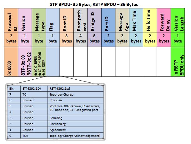
RSTP made slight changes in the BPDU format of 802.1D. In contrast to the topology change (TC), and topology change acknowledgment (TCA) flags of the 802.1D, it uses all 8 bits of the flag byte. The BPDU of RSTP is the version-2 BPDU. The switches running on STP 802.1D will drop this BPDU. The BPDU of RSTP consists of:
BPDU fields
Fields without a Change
- The Protocol ID field is a 2-byte field set as 0x0000 for both STP and RSTP.
- Root ID is the identifier of the root bridge, an 8-byte field. It consists of a 2-byte priority number followed by a 6-byte MAC address.
- The root path cost field shows the cost of the path from the bridge to the root bridge.
- The bridge ID is an 8-byte field signifies the ID of the switch originating the BPDU. Please refer to the previous article on STP for the 8-byte structure explanation.
- Port ID is a 2-byte field, the port ID for the wired link is 128, by default. It signifies the port ID of the port sending the BPDU.
- The message age field is set to zero by the originating switch. Each switch in-route will add 1 to this value. The receiving device will come to know the number of devices in the path. It is a 2-byte field.
- Max time is the time that indicates the validity of BPDU. In STP, it is 20 sec, and in RSTP, it is 6 sec by default.
- The hello-time is 2 sec for both the protocols, by default.
- Forward delay signifies the period the switch should wait for the transition to the next state.
Fields with a Change
- The second is the version, which is a one-byte field. It has the value 0x00 for STP; and 0x02 for the version-2 BPDU in RSTP.
- The third field is a message type field, which can have values 0x00 for the Configuration-BPDU and 0x80 for Topology Change Notification- BPDU in 802.1D. In 802.w it has the value 0x02.
- The flag is a 1-byte field, STP uses only two bits of them. However, in RSTP makes use of all eight bits.
- The version length is an additional one byte is in RSTP BPDU. It has a value 0 in RSTP, indicating that no version one protocol information is present.
RSTP Flags
As you can see in the image, the RSTP retains the first and last flag bit as in STP. The other bits define the role and state of the port originating the BPDU. It also manages the proposal and agreement mechanism.
The bits 7 and 0 are used for topology change and topology change acknowledgement.
Bits 1 and 6 are used for proposal and agreement procedure. RSTP uses a synch mechanism, where each switch sends its BPDU to the neighbor even if it is not getting BPDU from the root bridge. Hence, the convergence between neighbors occurs very fast.
Bits 2,3,4, &5 are used for conveying port status and the port roles as shown in figure.
The RSTP does not have separate BPDU for the topology change(TCN-BPDU) as in STP 802.1D. It just uses the 8th-bit (bit number- 7) of the flag as a topology change. However, for inter-operability with the old 802.1D protocol, the RSTP may process or generate the TCN-BPDU.
RSTP timers
The root bridge in 802.1D sends BPDU in every hello-time (2 sec by default), which is relayed by the other switches. In RSTP, all switches generate their BPDU in every hello-time even if they don’t receive it from the root bridge.
The aging time is now three hello-time unlike 802.1D where it was ten times of hello-time. If a switch misses three consecutive BPDUs, it will consider that it lost the link. The fast aging allows the switch to detect the fault in less time.
As we have discussed in STP, the inferior BPDUs are ignored for 20 sec. Whereas in 802.1w, the neighbor switch responds to the inferior BPDU. It will reply to the switch with inferior BPDU, the information about the root bridge. As a result, it will stop sending the BPDU; and updates the root port.
Please see the image below:
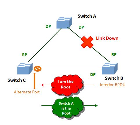
As the link to the root port breaks, switch B will send the inferior BPDU to Switch C. Switch C will respond and send the information of the root bridge to Switch B. Now switch B will stop sending that BPDU and accepts Switch A as the root bridge. It also changes the root port through the alternate port.
There is a change in path cost as well. We have already discussed the path cost comparatively in our previous chapter. Refer to the path cost table in this article for RSTP path cost.
Rapid transition to forwarding state
The convergence of RSTP is faster. It waits for six sec to the BPDU in the link since the max_age is three hello-timer. In the case of the root bridge link failure, the switch will temporarily block all the ports. This blocking will ensure that no loop is creation is there. It will then communicate with the neighbor by sending a proposal. The port will not go for the listening state in RSTP. The port on learning goes directly to the forwarding state in a few seconds.
The BPDU in RSTP works as a keep-alive mechanism. Aging time is just 3- hello-timer in RSTP, which allows for fast failure detection. The switch will transit its port to an appropriate state very fast, depending upon the proposal and agreement with the neighbor.
Final topolgy in STP and RSTP are the same
The path calculation mechanism in RSTP is the same as the legacy STP. The only difference is in the path cost, which is revised to accommodate higher-speed links in RSTP. The final topology will be the same, but the way to achieve it is different. It will use the proposal and agreement mechanism between neighbors to achieve the convergence, a method known as synch in RSTP.
RSTP does not depend on the timers to move a port from one state to another; rather, it uses a negotiation mechanism by proposal and agreement to decide it.
RSTP also incorporates the concept of the edge ports. Edge ports are not connected to switch at another end, or they have connectivity to the hosts. These ports will directly transit to the forwarding state. The protocol can mark the edge ports automatically if no BPDU is received from the other end. If the port is connected to a switch later, it will start receiving BPDU from that end. Then RSTP will identify the port as a non-edge port.
4. Rapid PVST and Rapid PVST+
They are the Cisco modification/ improvement on the RSTP standard. Like PVST, the Rapid PVST allows multiple VLANs over the ISL trunk. It supports rapid convergence with multiple VLANs. It will have a different spanning-tree instance for each VLAN.
Rapid PVST+ allows 802.1q trunks to communicate with the Rapid PVST link like PVST+in the previous case. It ensures the inter-operability between Rapid PVST and RSTP regions.
5.MST (IEEE 802.1s)
Multiple Spanning-Tree provides multiple instances of spanning tree with Rapid convergence. It combines the feature like PVST+ of load balancing between multiple VLANs and rapid convergence like 802.1w. The 802.1s is backward compatible to the 802.1D and 802.1w.
Unlike PVST, where you have one spanning-tree instance for each VLAN, you can combine multiple VLANs to a single spanning-tree in MST. If you have 100 VLANs in PVST, you must have 100 spanning-tree instances. But in MST, you may have 2 VLAN instances each for a group of 50 VLANs. MST efficiently saves the CPU/Memory use at the same time provides load balancing through two paths.
We will discuss the configuration part of Spanning Tree Protocol in the next article. Please comment on the bottom of the page to give your feedback. Thank you for reading.
Take a Quiz on this topic :
