In the last two articles, we have thoroughly discussed the STP and its types. Let us now go for the Spanning Tree Protocol configuration. In this chapter, we will cover the PVST and RSTP in detail. I am going to demonstrate the labs in the Cisco packet tracer. Please go through the chapters Spanning tree protocol and Types of STP before trying this configuration part. I hope this article will be helpful to clear all the doubts and make you understand the concept clearly.
Spanning Tree Protocol configuration : Case analysis
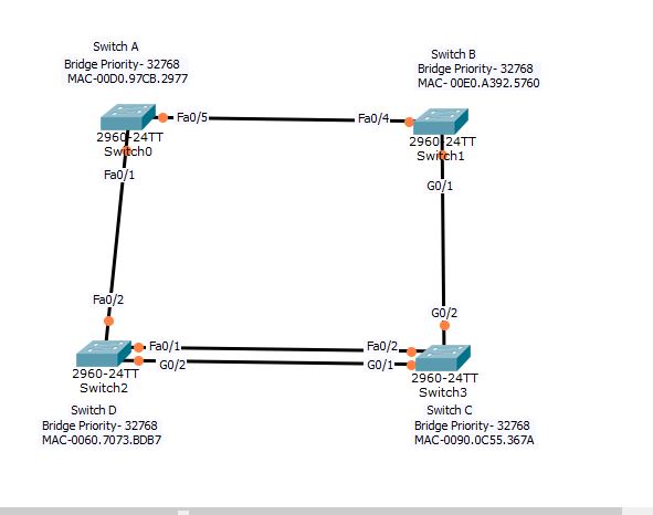
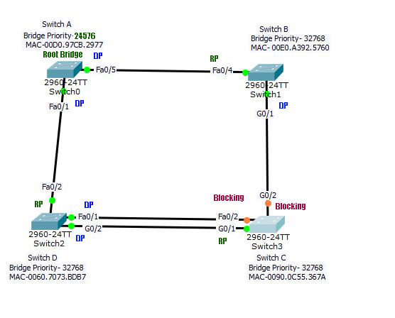
In the above picture, check all the Bridge IDs and links. Which switch will be the root bridge?
Root bridge: From the MAC addresses given, Switch D is the root bridge.
Root Ports:
- In switch A, Fa0/1 has a cost 19 to the root bridge, and Fa0/5 has cost 19+4+4= 27. Hence Fa0/1 is the root port.
- In switch B, Fa0/4 has a cost 19+19=38, and G0/1 has cost 4+4=8. Hence G0/1 is the root port.
- Now look at the switch C, it has 2 paths to the root bridge; Fa0/2 with a cost 19 and G0/1 with a cost 4. Obviously, G0/1 is the root port.
Designated Ports:
In switch D, the root bridge; Fa0/2 and G0/2 are designated ports. In switch, C G0/2 is the DP. Now, one port from the Switch B- Fa0/4 and Switch A- Fa0/5 should be the DP. Similarly, Switch B-F0/1 and switch C-F0/2 will have one DP. Let’s see, which port wins the bid for the DP, and which port goes to the blocking mode.
Between switch A and switch B, first check the cost to the root bridge. Switch A has a cost 19 and Switch B has a cost 4+4=8. Hence, switch B-Fa0/4 will be the DP and switch A-fa0/5 will be the blocking port.
Similarly, between switch D-Fa0/1 and switch C-Fa0/1, the first one will be the DP since its on the root bridge with a cost 0.
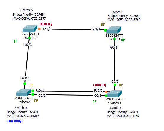
Look at the image below for solution.
Spannig Tree Protocol configuration basic commands
By default, the Cisco catalyst switch would configure the PVST mode. It will create different instances of STP for each VLAN. You may configure PVST, Rapid PVST, or MST (Multiple Spanning Tree) in those switches. In multiple spanning-tree configurations, you may have multiple STP instances each representing a group of VLANs. The following table shows the Basic Spanning tree protocol configuration commands:
| No | Command syntax | Function | Explanation |
|---|---|---|---|
| 1 | switch(config)#spanning-tree mode pvst|rapid-pvst|mst | You can set the spanning-tree mode to PVST, rapid PVST, or MST | Default is PVST |
| 2 | switch#show spanning-tree | Displays the parameters of spanning-tree | Root ID, Root path cost, Bridge ID, Timers, Interface status, etc. |
| 3 | switch(config)#spanning-tree vlan <vlan_id> priority <priority_number> | To set the priority of a switch for a VLAN | Priority is 32768 by default. It can be set 4096 to 61440 in increments of 4096. VLAN_ID is 1-4094 |
| 4 | switch(config)#spanning-tree vlan <vlan_id> | Enable spanning-tree for a VLAN | VLAN_ID can be 1-4094 |
| 5 | switch#show spanning-tree vlan <vlan_id> | Displays the parameters of spanning-tree for a particular VLAN | Same as row 2 |
| 6 | switch(config)#spanning-tree vlan <vlan_id> root primary | Set the switch as root bridge for a VLAN | You can bypass the root bridge election by directly assigning a root bridge |
| 7 | switch(config)#no spanning-tree vlan <vlan_id> | negates the command of creating spanning-tree | deletes the spanning-tree for a VLAN (1-4094) |
| 8 | switch#show spanning-tree vlan <vlan_id> root | Displays the information of root bridge of a VLAN | Bridge ID, cost to the root bridge, interface root port, etc. |
| 9 | switch(config-if)#spanning-tree vlan <vlan_id> port-priority <0-240> | Assign priority manually to any interface | From interface config mode. <0-240> port priority in increments of 16. |
| 10 | switch#show spanning-tree interface <interface_id> | Shows the status of the port | Role, status, cost, priority, neighbor, etc. |
| 11. | switch(config)#spanning-tree vlan <vlan_id> root secondary | Set the switch as secondary root bridge for a VLAN | It will function as root bridge in case of failure |
Verify the STP
Let us first verify the default STP running on the network. Then, we will manipulate the parameters to check them. Run the command show spanning-tree in Switch-A.
Switch#show spanning-tree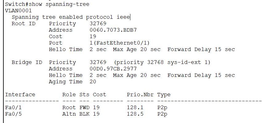
- Spanning-tree is enabled for VLAN 1.
- Root bridge ID is the priority+ system ID extension with the MAC address of the Root Bridge (here Switch-D).
- The cost to the root bridge is 19 via Fa0/1.
- Timers are as default.
- Bridge ID is the ID of the switch itself. Priority, MAC address, and timers set as default.
- Interface Fa0/1 is the root port, Forwarding state. Port-priority is 128, the port number is 1, type peer-to-peer.
- Interface Fa0/5 is an alternate port, blocking status. Port priority is 128, the port number is 5, p2p.
Manipulate the STP parameters
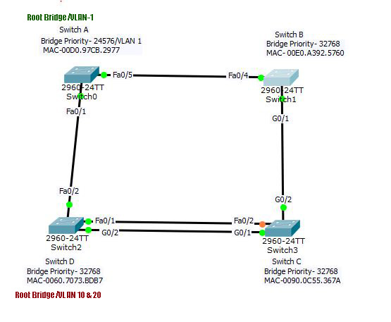
Configure switch A as the root bridge:
Switch(config)#spanning-tree vlan 1 root primary Now check the parameters again.
Switch(config)#end
Switch#show spanning-tree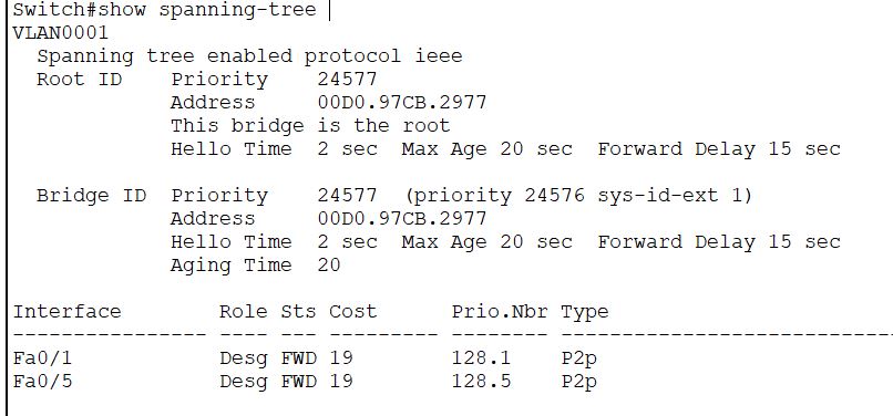
- See the Root ID is changed. It has assigned a priority lower than the default 32768 and in multiples of 4096. The new priority is 24576+System ID extension(1), i.e., 24577.
- Timers are unchanged.
- See the interface status, both are designated port now.
- You can also assign a secondary root bridge for VLAN with the command in row 11 on the table.
- You can use another method to elect a root bridge by assigning it a lower priority with the command given in row 3 of the table.
- Also, try other commands from the above table, like changing the port priority.
Change port priority: Example
Switch(config-if)#spanning-tree vlan 1 port-priority 10
% Port Priority in increments of 16 is required
Switch(config-if)#spanning-tree vlan 1 port-priority 16
Exercise
Now let’s do a little exercise. Can you go back to figure B and figure out the new blocking ports, designated ports, and the root ports?
- Switch B-Fa0/4 is the root port. Similarly, Switch D-fa0/2 is the root port.
- What about switch C? The cost of G0/2 is 23, and that of G0/1 is also 23 to the root bridge.
- The FastEthernet link between switch C and D will be disabled. Since the cost to the root bridge is lower from switch D, Switch C-Fa0/2 will be in blocking mode.
- The next bid is between the Gigabit link of Switch C and D vs B and C. One link should be disabled.
- The cost to root from Switch B and D is the same. And the cost from Switch C to the root bridge via G0/1 and G0/2 is also the same.
- Now check the MAC address switch B has the highest, and that of switch D is the lowest. Hence, the link between B and C will be disabled. But which port?
- Switch B has a cost to the root bridge better than C. Hence, switch C-G0/2 will be blocking.
Now lets check the port status of the switch C.
Switch#show spanning-tree vlan 1
VLAN0001
  Spanning tree enabled protocol ieee
  Root ID    Priority    24577
             Address     00D0.97CB.2977
             Cost        23
             Port        25(GigabitEthernet0/1)
             Hello Time  2 sec  Max Age 20 sec  Forward Delay 15 sec

  Bridge ID  Priority    32769  (priority 32768 sys-id-ext 1)
             Address     0090.0C55.367A
             Hello Time  2 sec  Max Age 20 sec  Forward Delay 15 sec
             Aging Time  20

Interface        Role Sts Cost      Prio.Nbr Type
---------------- ---- --- --------- -------- --------------------------------
Gi0/2            Altn BLK 4         128.26   P2p
Gi0/1            Root FWD 4         128.25   P2p
Fa0/2            Altn BLK 19        128.2    P2p
Note that the port number of G0/1 is 25 and that of G0/2 is 26 as they come after the F0/24 port. See, G0/2 and Fa0/2 of the Switch C are in blocking. The new topology will look like the following:
Per VLAN STP instance configuration
- Create VLANs 10 and 20 in all the switches.
- Convert all the active ports into a trunk port. For the help in the creation of VLANs and trunk port, please refer to the blog VLAN configuration.
- Select the root bridge for each VLAN either by priority or root command.
Enable PVST+
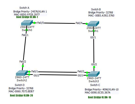
Now we will continue from the topology in Figure C. Switch A is the root bridge for VLAN-1. We will make Switch B, the root bridge for VLAN -10 and let VLAN 20 to select root bridge by itself. I will show you step by step commands.
Step 1. Create VLAN
Switch(config)#vlan 10
Switch(config-vlan)#ex
Switch(config)#vlan 20
Repeat this step in all switches. Now go to Switch A and Switch C to change the interfaces to trunk mode. Switch B and D will automatically have the configured trunk ports. You can verify the spanning-tree of created VLANs here. It will show something like this. You can check the same for other VLANs; there will be only STP running for VLAN-1.
Switch#show  spanning-tree vlan 10

No spanning tree instance exists.

Switch#
Run the following command in Switch A
Switch(config-vlan)#Switch(config)#interface range f0/1, f0/5
Switch(config-if-range)#switchport mode trunk
Now configure trunk in Switch C
Switch(config)#interface range f0/2, g0/1-2
Switch(config-if-range)#switchport mode trunk
Now you can verify the trunk ports in each switch. All the trunks are created, with 802.1q encapsulation. Now from any of the switch, check the Spanning-tree. There will be three instances of spanning-tree. VLAN 1 has the root bridge Switch-A. As the priority of the Switch A is set for VLAN 1 only, VLAN 10 and 20 will elect the root bridge, which is Switch C with the lowest MAC address. The topology will look like this:
Change the bridge priority for VLAN
Go to the switch-C now and set it’s priority lowest for VLAN-10.
Switch(config)#spanning-tree vlan 10 priority 4096Now the VLANs and Root bridge are as under:
- First instance: VLAN 1- Switch A, priority -24576+1=24576
- Second instance: VLAN 10- Switch C, priority- 4096+10=4106
- Third instance: VLAN 20- SwitchD, priority-32768+20=32788
- You may find all the ports green in this topology because a port blocked in one STP instance may be forwarding in another instance.
The complete spanning-tree is as shown as below. The port status is different in different switches. You may check it at each switch.
Switch#show spanning-tree
VLAN0001
  Spanning tree enabled protocol ieee
  Root ID    Priority    24577
             Address     00D0.97CB.2977
             Cost        23
             Port        25(GigabitEthernet0/1)
             Hello Time  2 sec  Max Age 20 sec  Forward Delay 15 sec

  Bridge ID  Priority    32769  (priority 32768 sys-id-ext 1)
             Address     0090.0C55.367A
             Hello Time  2 sec  Max Age 20 sec  Forward Delay 15 sec
             Aging Time  20

Interface        Role Sts Cost      Prio.Nbr Type
---------------- ---- --- --------- -------- --------------------------------
Fa0/2            Altn BLK 19        128.2    P2p
Gi0/2            Altn BLK 4         128.26   P2p
Gi0/1            Root FWD 4         128.25   P2p

VLAN0010
  Spanning tree enabled protocol ieee
  Root ID    Priority    4106
             Address     0090.0C55.367A
             This bridge is the root
             Hello Time  2 sec  Max Age 20 sec  Forward Delay 15 sec

  Bridge ID  Priority    4106  (priority 4096 sys-id-ext 10)
             Address     0090.0C55.367A
             Hello Time  2 sec  Max Age 20 sec  Forward Delay 15 sec
             Aging Time  20

Interface        Role Sts Cost      Prio.Nbr Type
---------------- ---- --- --------- -------- --------------------------------
Fa0/2            Desg FWD 19        128.2    P2p
Gi0/2            Desg FWD 4         128.26   P2p
Gi0/1            Desg FWD 4         128.25   P2p

VLAN0020
  Spanning tree enabled protocol ieee
  Root ID    Priority    32788
             Address     0060.7073.BDB7
             Cost        4
             Port        25(GigabitEthernet0/1)
             Hello Time  2 sec  Max Age 20 sec  Forward Delay 15 sec

  Bridge ID  Priority    32788  (priority 32768 sys-id-ext 20)
             Address     0090.0C55.367A
             Hello Time  2 sec  Max Age 20 sec  Forward Delay 15 sec
             Aging Time  20

Interface        Role Sts Cost      Prio.Nbr Type
---------------- ---- --- --------- -------- --------------------------------
Fa0/2            Altn BLK 19        128.2    P2p
Gi0/2            Desg FWD 4         128.26   P2p
Gi0/1            Root FWD 4         128.25   P2p
Few more Show commands
| 1 | #show spanning-tree active | Shows spanning-tree active interfaces only |
| 2 | #show spanning-tree summary | Displays spanning-tree mode, and other summaries. |
| 3 | #show spanning-tree interface <interface_id> | Shows the STP instances associated with that interface |
| 4 | #show spanning-tree vlan <vlan_id> | Shows the spanning-tree instance of specific VLAN |
Enable Rapid-PVST/PVST+
Run the following command in each switches. You can experience the change in convergence time reasonably. Also check the spanning-tree mode by show spanning-tree summary command.
switch(config)#spanning-tree mode rapid-pvstPlease give your comments, if you liked this article. Follow our social media links to stay updated. Join our Facebook page from the icon at the top. You can also follow the Pinterest profile to access the article from the featured image at a single click.