The spanning tree protocol or the STP is the protocol used to resolve and eliminate the loops when there are multiple switches in a network with redundant paths. When there are multiple paths between the network switches, and any destination has more than one possible pathway, then the problem known as bridge looping may occur. STP addresses this problem by blocking the redundant path and also restores the route in the case of another route failure.
STP provides redundancy of the path; at the same time, it also manages the loop issues. We will discuss in detail how does the spanning tree protocol decides to block the port(s) and what are the different versions of STP.
Types of Spanning Tree Protocol
Let us have a look at the different versions of the STP. The different versions of STP are:
- The 802.1D, original STP: A slow convergence standard in today’s scenario.
- PVST(Per VLAN Spanning Tree): The Cisco version, or an improvement over 802.1D, that allows different Spanning tree for each VLAN. The extension PVST+ is one that supports dot1q interoperations besides the proprietory ISL. Convergence is still the same.
- RSTP( Rapid STP): New version of the original STP, that addresses the convergence problem. Standardized as 802.1w, it provides much faster convergence.
- Rapid PVST/ PVST+: Again, the Cisco proprietary, improved version of RSTP added with per VLAN feature. The extension PVST+ is interoperable with the dot1q as earlier.
Need of STP
When multiple switches are connected in redundant ways, the following consequences arise:
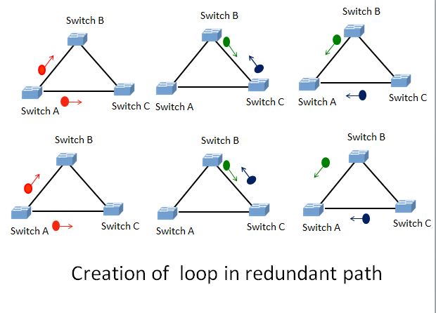
Broadcast storm: Whenever a Layer-2 switch gets a broadcast frame or a frame with an unknown destination MAC address, it floods the frame to all ports except one from where it received the frame. You can see in the above image what happens when Switch-A sends a broadcast frame to the switch B and C. B will send the frame to C and C to B. Again both of them will send it to A. A in turn, sends the frame received from B to the switch C considering it as a different frame. At the same time, it will also send the same frame received from C to switch B.
With those duplicate frames growing more and more further, an infinite loop of frames forwarding develops. The loop will stop only if someone manually removes a link or a Switch from the circuit, or one of the switches breaks down. This condition is called the broadcast storm.
Duplicate Frames: The host connected to the switches will get the same frame repeatedly since it comes from either way.
Unstable MAC table: The switches have to update the MAC table every time it receives the frame from other links.
In absence of the Spanning Tree, the network will choke down, due to the flood. The STP simply blocks one of the ports. The selection of port to be blocked is governed by a series of events, which I am going to explain in detail.
Operating modes of switch-port
Before going in the detail, let us first understand a few terms related to the switch operation. There are five states of port operations. The ports can move from one mode to another in a sequence and with a time limit. They are:-
Disabled: A port in the disabled state does not participate in any operation of the network at all. It is in the shutdown state.
Blocking: A port in the blocking mode discards the frames but listens to the BPDU, to get the message of the spanning tree algorithm. It may go to the forwarding state if any other link in the network fails. Though, it goes to the forwarding mode via the listening and learning modes. It does not learn the addresses.
Listening: It also discards the frames, receives BPDU, does not populates the MAC address. It is the first state when a blocking port transits towards the forwarding state. It takes 15 seconds in this state before the transit to the learning state.
Learning: The interface in the listening state enters the learning state before going to the forwarding state. This port discards frames receives BPDU and learns MAC address. Here the interface is preparing to participate in the forwarding role. It also takes 15 seconds to transit from learning to the forwarding state.
Forwarding: This is fully functional port. It listens, makes MAC table and also forwards the traffic.
Spanning Tree Protocol terminology
In STP, you are also going to encounter those terms. Since the original STP 802.1D was standardized in 1990, you will find the term bridge in STP, treat them as equivalent to switch in this context. Let us go through these terms, as well.
BPDU (Bridge Protocol Data Unit): These are the data frames used by the STP protocol to exchange data related to STP information. There are two types of BPDU, first is the Configuration BPDU and the second is Topology Change Notification (TCN) BPDU.
Root Bridge: The root bridge is one of the switches in network elected as the root (chief) by the spanning tree algorithm. We will see how does it happen in the following sections.
Root Port: This is the forwarding port of a switch other than the root bridge, having a minimum cost path to the root bridge.
Designated port: This is the least path cost to the root bridge through the LAN segment. All the ports on the root bridge are the designated ports.
Non-Designated ports: All other ports are non-designated ports which are in blocking state.
I will explain those ports in the following sections, as well.
STP path cost
The following table shows the path cost utilized by the original Spanning tree protocol (802.1D) and the RSTP (802.1w) for calculation of path for various links. The easy way to remember the Spanning tree cost for STP is “1 Gbits/sec”/Bandwidth, which is valid for the first three entries. In the third entry, it’s 1000/16= 62.5, rounded to 62. Rest are adjusted since it would not have permitted the Band width above 1 Gbps. For RSTP it’s “20 Tbits/sec”/Bandwidth, which is given in the table.
| Bandwidth | STP Cost | RSTP Cost |
| 4 Mbps | 250 | 5,000,000 |
| 10 Mbps | 100 | 2,000,000 |
| 16 Mbps | 62 | 1,250,000 |
| 100 Mbps | 19 | 200,000 |
| 1 Gbps | 4 | 20,000 |
| 2 Gbps | 3 | 10,000 |
| 10 Gbps | 2 | 2,000 |
| 100 Gbps | NA | 200 |
| 1 Tbps | NA | 20 |
Election of the root bridge in Spanning tree protocol
The switches Exchange one of the two types of BPDU, i.e., Configuration BPDU for spanning tree computation. Another BPDU type is the TCN (Topology Change Notification) BPDU. The configuration BPDU consists of the following fields.
- Root Bridge ID– This is the bridge ID of the Root bridge. Initially, each switch proclaims itself to be the root bridge and sends its own ID as the root bridge ID.
- Sender’s Bridge ID– It is the bridge ID of the station sending the BPDU. At the initial stage, it will be the same as the root bridge ID as each switch sends its own bridge ID as the root bridge ID.
- Cost to root bridge– It is the STP cost between the root bridge and sender, measured as per the STP cost table shown above. No need to say, the value is zero at first, as each switch supposes itself as the root bridge.
- Timer values on root bridge– This field consists of the hello_timer, max_age timer, and forward_delay timer. The default values are 2, 20, and 15 seconds respectively. In addition, it also contains the field message_age, which is set to a value ‘0’ by the root bridge, and each switch in route will add ‘1’ to this. Resultantly, the receiver will come to know its distance from the root bridge.
Composition of the Bridge ID
The Bridge ID is an eight-byte field containing 2 bytes of bridge priority and 6 bytes MAC address. The bridge priority is configurable in multiples of 4096. The default value of the Bridge priority is 32768 plus the VLAN ID. The spanning-tree computes (Bridge priority +VLAN ID) for the election of the root bridge. For the default VLAN, the number is 32769. See the image below for a clear understanding of the Bridge ID composition.
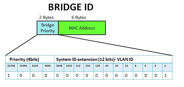
- Default value for VLAN 1 = 32768+1= 32769.
- The VLAN ID may have value 0 to 4095, a total of 4096 combinations in 12 bits.
- Since the bridge priority starts from the lowest bit with a place value 4096, it can only be configured in a multiple of 4096. The sum of all 16 place values is 65535, and that of 12 lower bits is 4095. By subtracting, you can find the maximum configurable value for priority, i.e., 61440. There are 16 possible values in the multiple of 4096 for priority configuration.
The Root bridge is the switch, which has the lowest Bridge ID. An administrator may plan a switch to be the root bridge by configuring the priority accordingly. If the priority of 2 or more switches is the same, then the MAC address is the tie-breaker. One with a lower MAC address will be the root bridge.
Election
At the initial stage, all switches in the network will send its BPDU, assuming itself as the Root Bridge. In the Root Bridge ID field, they will place their own bridge ID and the cost to the root bridge as zero. After receiving the BPDU of other switches, they will learn and agree to elect one with the lowest bridge ID as the Root. When a switch detects another switch having a better bid for the root bridge, it replaces the root bridge ID in its BPDU. it will also change the cost to the root bridge by calculating. The exchange of BPDU with other switches continues until all the switches in the circuit learn and agree to elect the switch with the best bid as the root bridge. The root bridge is a reference for all switches that decide port to be in blocking mode.
Selection of Root Port, Designated port and Non-designated port in Spanning tree protocol
Once the root bridge is elected, the ports will be selected as the root port, designated port, and the non-designated/blocking port. Let’s take an example.
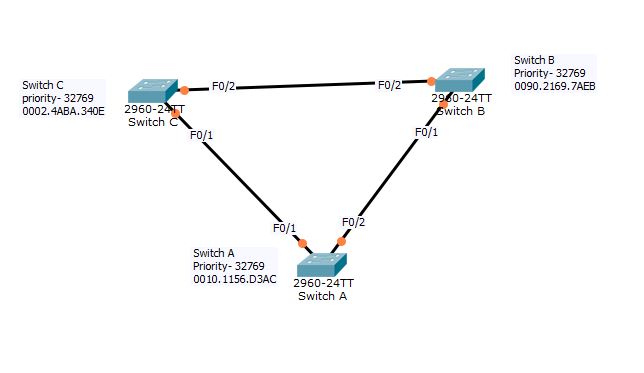
Examine the above figure there are three switches in a redundant path. The Spanning tree protocol should direct one of the ports to go to blocking mode. How does it perform this?
Step1-Elect Root Bridge
Election of the Root bridge: I hope you can figure out which switch is going to be the root bridge in the above circuit. Switch A, B, and C all have the same default priority. You can compare the MAC addresses now. As you can see, the switch C has the best bid with the lowest MAC address. Hence the Root bridge is switch C here.
Step 2-The root ports
Now, the BPDU from switch C will set the cost to the root bridge field as zero. It will send the BPDU to switch A and B.
In switch B, it will receive the BPDU from Switch C in F0/2 and will calculate the cost to the root bridge. The STP cost is 19 through F0/2, as it is fast ethernet (100Mbps). It will send BPDU to other ports specifying the cost to root bridge as 19.
Switch A will also learn the cost to the root bridge is 19 via F0/1. It will also receive the BPDU at F0/2 from the switch B. The cost to root via this link is 19+19= 38. Hence, F0/1 is the shortest route to the Root Bridge for the Switch A. It will designate F0/1 as the Root Port.
Similarly switch B will receive the BPDU from Switch A, and learn the cost to root bridge via both the ports. It will designate F0/2 as the Root Port.
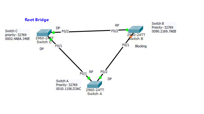
Step 3- Designated ports
All the interfaces connected to the root bridge will be in forwarding mode. Hence, F0/1 and F0/2 of Switch C are in forwarding mode. As the ports of the root bridge cannot be the root port, both of them are the Designated Ports.
So far, it is clear that one of the ports among Switch A-F0/2 and Switch B- F0/1 must go to the blocking mode. What are the factors deciding that? Both of them have the same cost to the root bridge.
Step 4: Blocking port
The sequence of the tiebreaker for the choice of the designated port and blocking port is:-
- The first is the lowest cost to the root bridge
- The second parameter is the lowest Bridge ID
- Then the lower value of the MAC address will be checked.
- If all of them ties then, the lowest neighbor port priority will be checked (128 by default, configurable in the multiple of 32, range 0 to 224).
- The last tie-breaker is the lowest neighbor port number.
The one which has the lowest among any of the above parameters will be the designated port. Another will be the blocking port.
Between Switch A-F0/2 and Switch B- F0/1, the first condition ties, the second also has tied, the third condition decides Switch-A- F0/2 to be the designated port, and the Switch-B F0/1 will be the blocking port. Now, look at the image below.
Show Sapnning-tree
Lets have a look on the spanning-tree of all the three switches. That will make the concept more clear.
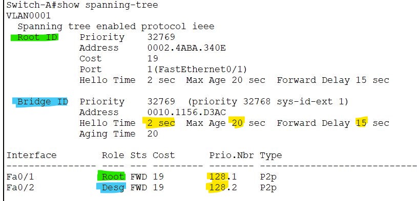
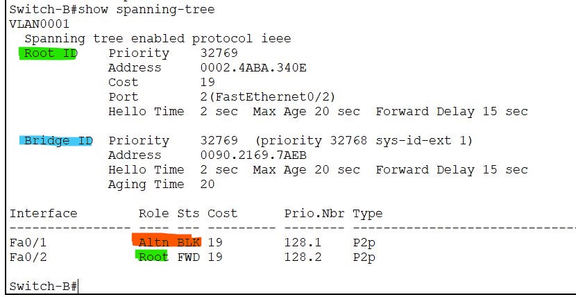
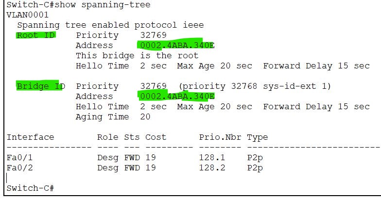
You can check the status by executing the command #show spanning-tree from privilege Exec mode. Now examine the images. The Root ID and the Bridge ID in Switch C are the same, whereas the other two switches designated Switch C as Root Bridge. The cost for Fast-Ethernet port is 19, the port priority is 128, as discussed earlier. The Root port, designated port, and blocking port are specified to each interface.
Now take another example:
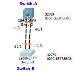
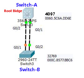
In the above Figures A and B, the Switch B has a better bid (in MAC addresses, 000C is less than 0060) than the Switch A; hence, the root bridge is the Switch-B. Now understand the selection of root port, designated port, and undesignated port here.
First, it will examine the cost to the root bridge, which is 4 for both the links. Now, it will inspect the bridge priority and the MAC address; both are identical as both links exist on the same switch. Now it will check the neighbor port-priority; both of them happens to be 128. The last tie-breaker is the neighbor port number. The G0/2 of Switch-A has a link to the G0/1 of the Switch-B. Hence, G0/2 of Switch-A wins the bid as it has a link to the lower neighbor port number. The deciding port number is not that of Switch-A, but the neighbor, which is, in this case, the Switch-B. Hence G0/1 of Switch-A goes to the blocking state.
Bridge ID manipulation
Now change the port priority by applying the following command. I am going to lower the port priority of the Switch-A.
Switch-A(config)#spanning-tree vlan 1 priority 4096
Switch-A(config)#do wr
Building configuration...
[OK]
Switch-A#show spanning-tree 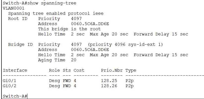
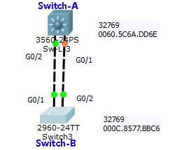
Now, show the spanning-tree, you can see now the Switch-A is the root bridge since its bridge priority is lower. You can check that the Root ID and the Bridge ID are identical. What will happen to the ports now?
The Gigabit ports 0/1 and 0/2 of the Root Bridge, which is the switch-A now, will be in forwarding state. One of the ports of Switch-B should go to the blocking state. The question is, which one?
One connected to the higher port number of the Switch-A will go to blocking mode since all other parameters are identical. Now the deciding port number is that of the Switch-A. Hence the port G0/1 of the Switch-B will go to the blocking mode, as it is linked with G0/2 of the Switch-A. The following image will demonstrate it more clearly.
The timer part is still not discussed. It shows the aging timer 20 sec, hello timer 2 sec, and forward delay 15 seconds. Let’s have a look at the timers.
Convergence in Spanning tree Protocol
There are various timers specified in STP. The hello timer is of 2 seconds, and the max-age time is ten times the hello timer, i.e., 20 seconds. The forward delay is 15 seconds. In case of topology change, any link break, etc., the STP takes 50 seconds to rebuild the topology. In some cases, it may be as good as 30 seconds.
Direct link
Refer to figure D above. If a switch having two links to the root bridge, one is in blocking mode; detects the active link failure, it will switch to alternate port, i.e., the blocking port. It will take 2×15= 30 seconds for the port to go to the forwarding state from the blocking state. It will take 15 seconds in listening and 15 sec in learning before going to the forwarding state. If G0/2 of the Switch-B fails, it will set G0/1 to the listening mode by itself.
In the same condition, if the Switch-B does not detect it immediately, it will continue with the old BPDU information at Port G0/1 till the max-age, i.e., 20 seconds. This situation may happen in case its connectivity is through an intermediate device like a hub. After 20 seconds, the old BPDU will expire. Now, it will send the blocking port to forwarding mode. Thich takes another 15x 2 seconds transition time. That is a total of 50 seconds for the convergence.
Indirect Link
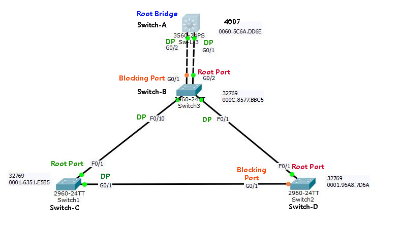
Please refer to Figure E above. If the F0/1 of Switch-C fails, it will stop getting any BPDU. Since its root port is down and another port is in blocking state at Switch-D. Now it will start sending BPDU pretending itself as the Root Bridge. The Switch-D still linked to the Root bridge through F0/1 and is receiving the BPDU from the root bridge Switch-A. Hence, it ignores the BPDU of Switch-C, as it is inferior BPDU for Switch-D. After 20 seconds, it responds to the BPDU from Switch-C and puts its port G0/1 in the listening state. Now, the Switch-C will get the relay BPDU from Switch-D, which is coming from the Switch-A, the root bridge. After realizing the Switch-C again changes the value of Root ID and designates its G0/1 port as the Root Port. It will take a time of 50 seconds for the network to converge.
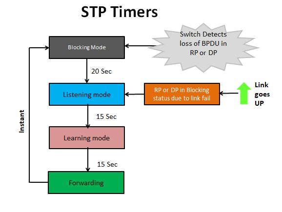
Look at the image below, it tells you about the timers in a brief note. A switch port in the Blocking mode will be triggered when the switch detects a loss of BPDU in designated port/ root port. It will take 50 Sec transition time to reach Forwarding mode. When an RP/DP wakes up after a link failure, it takes no time to go to the listening mode then it will take 30 secs to the forwarding state. Meanwhile, the undesignated port will instantly go to the blocking mode from forwarding mode, when the designated port restores.
For the other versions of STP, please read the article Types of STP.
Take a Quiz on this topic :