Networking hardware devices are the devices used in the network for traffic forwarding and delivering. There are various types of Networking Hardware devices used and their use depends on the type, architecture, size, services, etc. of the Network. All of those Networking Hardware devices have a specific task and use. Let’s have a look at them one by one and let’s also see some sample networks with the utilization of those devices.
You may have heard all or at least a few of their names, may also know a little about them. I will try to explain each of them in my own words, so that readers may get a clear concept of their work and purpose.
Lets first make a list of those devices :
- NIC (Network Interface Card)
- Repeater
- Hub
- Bridge
- Switch
- Router
- Modem
- Gateway
Let us discuss all those devices one by one. If you have any queries related to the topic, you can comment on your question. After finishing the chapter don’t forget to give a try to the quiz.
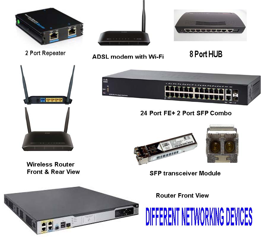
Different Networking Hardware Devices
NIC (Network Interface Card)
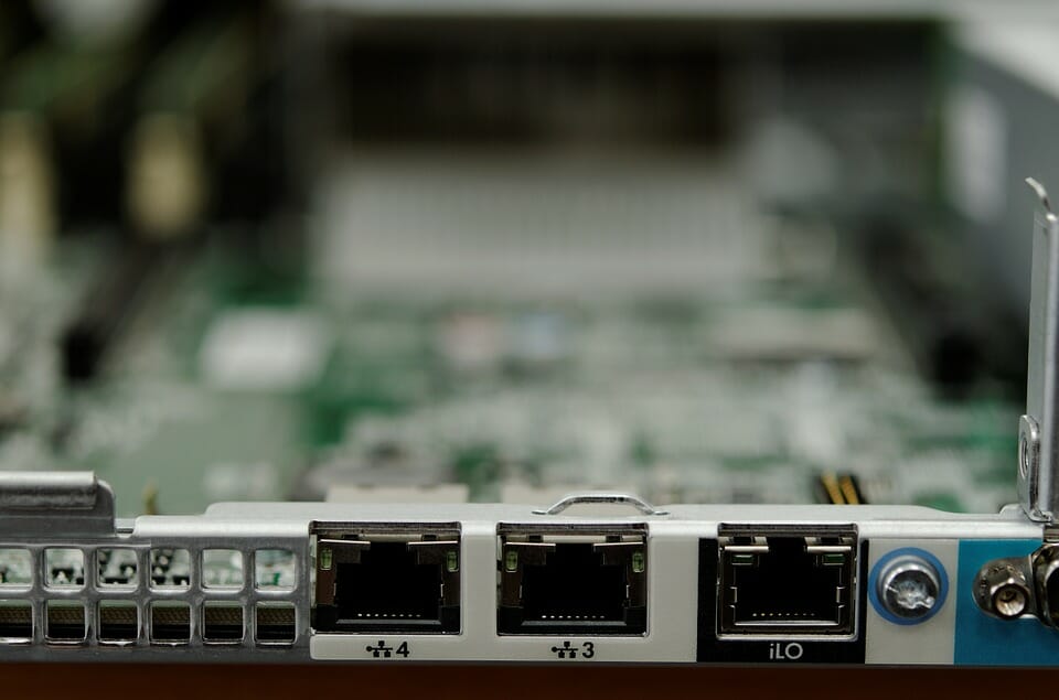
A Network Interface card is known by various names. A Network Interface Controller, LAN adapter, Ethernet Card, etc. This comes with every PC hardware integrated with Motherboard or can be in the form of an Add-on card. Each NIC has a unique MAC address. There are various speed versions like 10/100 Mbps, 1 Gbps, 10 Gbps. The NIC comes with an RJ-45 female socket and 2 numbers of LED indicators in most of the cases. The speed, Transmission Modes (Simplex/Duplex), etc. parameters are automatically negotiated when you connect it to a Network. This is the basic essential piece of hardware you need a PC to Network. High-end PC’s and servers may have multiple Ethernet Adapters.
Repeater:
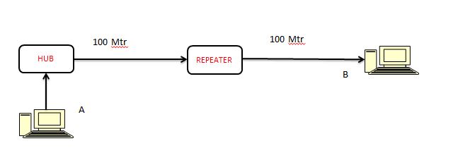
A repeater is a device that receives data before it becomes too weak, noisy, or corrupted, regenerates it, and transmits. When a UTP wire segment is lengthier than 100 meters, the signals will get corrupted due to attenuation, loss, and noises. This signal needs to be regenerated before transmitting further distance. Hence a repeater is conceptually equivalent to an amplifier used in analog cable TV line. Though, the function with the digital signal is regenerating rather than amplifying.
A repeater has two ports and it works in layer 1, i.e., Physical layer of OSI 7 layer reference module. It also requires a power supply to regenerate the signal. If the signal is represented by 0 V and 5 V levels, the errors in voltage level due to loss or attenuation will be refurnished by the repeater to the original value i.e. 0 and 5 Volts back.
It was useful in the coaxial network to overcome the distance restriction. However, in a star topology, the use of hub/ switch eliminates the need for a repeater, except special cases. The following diagram illustrates the function of a Repeater.
Hub or An Ethernet Hub
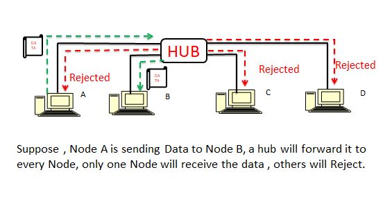
A hub can be said as a multi-port repeater. It is the central part of all nodes. All the hosts are connected like bi-cycle spoke with the hub (Not in a systematic manner though). It also functions in Layer 1 and broadcasts the Ethernet frames to all the nodes. The one which is supposed to receive will retain that, and others after checking the address will discard that signal.
See the sketch below to understand the function of a Hub. It receives a message from Node A to Node B. The data is forwarded to all stations. Everyone received it, but all stations rejected the message except Node B.
Collision Domain and broadcast domain:
Collision Domain: A collision domain is the part of a network segment where packets/ data may collide. If a number of nodes in a network segment transmit simultaneously, a collision occurs. If the data collide, it gets corrupted and needs to be re-transmitted. This reduces the efficiency of the network. In some cases, an excessive collision may result in the network to cease function.
Collision is likely to occur in a network with a hub. As shown earlier, the hub broadcasts each and every Ethernet frame. If the network grows bigger, hub maybe not capable of handling the network.
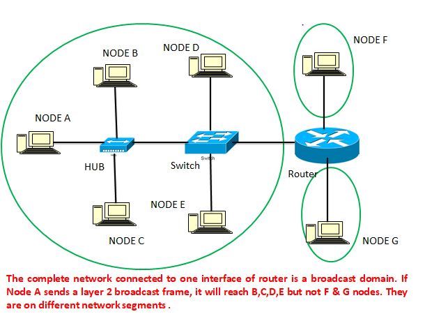
Broadcast domain: A broadcast domain is that segment of the network where any node can communicate with others with a Layer 2( Data Link Layer) Broadcast. In simple words, when a layer 2 device like Bridge and switch sends a broadcast frame, it will reach all the nodes of that segment. This thing will be more clear when you come to the next division Bridge and Switches.
For a hub, there is no difference between the Collision domain and the Broadcast domain. It broadcast every frame even if it is destined for only one node. Since each transmission is a broadcast transmission in a hub network, the complete broadcast domain is the collision domain.
In the next section, I shall describe other devices in terms of these two domains.
Please observe the image below to understand the Collision and Broadcast domain.

Bridge
The bridge is the device that aggregates multiple network segments or networks to create a single aggregate network. This function is called as Bridging. Don’t get confused with the function of the router, which summarizes the multiple routes, Bridging does not keep the networks independent or separate rather treats them as a single network.
It is because the Bridge functions in the Data Link Layer of the OSI module whereas Router works in Layer 3.
There are three types of Bridging:
- Simple Bridging
- Multi-port Bridging
- Transparent Bridging
Simple Bridging.
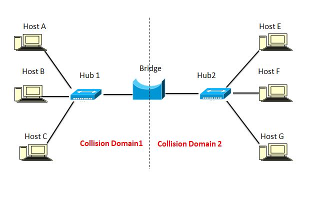
The conventional Bridging we know between two segments is known as Simple Bridging. Earlier, a big LAN used to be divided into two segments to minimize the collision. It used to divide one large collision domain into two within a single Broadcast domain. It was just like using a 2 port switch. With the use of Switched LANs, this concept has no relevance.
In this method, the Bridge uses a filter and forward method. Filtering occurs when both the communicating nodes are on the same side of the bridge. In that case, the frame is not forwarded to another side. Whereas when the bridge passes the frame to the other side, it is called forwarding. If the Host A wants to talk with Host C, the frame remains in collision domain 1 only as in the figure below.
Transparent Bridging
Transparent Bridging uses the Flooding method to maintain the table. The table is empty at the start and as the bridge receives frames, it will add the entry. If the destination Mac address is not available in the table it floods the frame to all other ports expect source port. The destination host will respond and then the entry will be made in Forwarding Information Base Table. This method ensures no frame is missed even if the entry is not in the Forwarding information base.
Multiport Bridging
The multiport bridge provides an interface for multiple networks. Multiport may also contain the Wireless LAN as one of the networks, then it is called a wireless bridge. The bridge decides frame by frame basis either to forward traffic or not and if yes where to forward it. It works in -“store and forward” method. They are equivalent to basic ethernet switches with some basic differences. The main difference is Bridge connect one port to a LAN with multiple MAC address whereas Switch connects each port to a NIC with one MAC address.
Switch
A Switch is a device that connects multiple devices in a network segment. It is a Layer 2 device, which means it works in the Data Link layer and forwards the frames to the destination device using the MAC address. Unlike the hub which sends the frame to all devices in the network segment, the switch takes intelligent decisions.
Refer to the image of Collision Domain earlier in this chapter, each segment of Switch is a collision domain. Or you may say switch divides the broadcast domains to the number of collision domains equal to its segments. It is the center point device in a Star topology just as a hub but takes smart decisions to differentiate itself from a hub.
The switch by default works in Layer 2, but special switches are known as Layer 3 (Network Layer) or Multilayer switches also operate in Layer 3.
We may classify switches in two basic types:
- Unmanaged Switch
- Managed Switch
Unmanaged switch
Unmanaged switches are designed to work as Plug-and-Play devices. Even the managed switch also works like that, but in an unmanaged switch, you can’t add additional functionalities. It doesn’t either provide a console port from where you can access the console for configuration.
The unmanaged switch comes pre-configured, and useful for basic connectivity. You can use them in home networks, or any other area where security, performance, management, etc. are not very much essential or cannot be afforded. All the unmanaged switches work in Layer-2 only.
Managed switch
Managed switch, on the other hand, provides a console port. The console port is a Serial communication port which you can connect with a COM port of PC and access from the terminal. You may configure various attributes like VLAN, Port mirroring, port security, Spanning Tree Protocol, QoS (Quality of Service), etc. We shall cover these aspects in another topic. Simply, Managed switches are manageable while unmanaged are not.
Managed switches may be Layer-2 switch as well as Layer-3 switches. Layer -3 switches are high-end switches with routing functionality. All managed switch cannot perform the task of Layer-3. But as far as a Layer-3 switch is concerned, it must be managed one.
Layer- 3 switches are commonly used for Inter VLAN Routing. For this particular function, a Layer 3 switch is more affordable than a router but remember the Layer-3 switch is not a replacement of the router. The router has many more functionalities which a Layer-3 switch cannot perform.
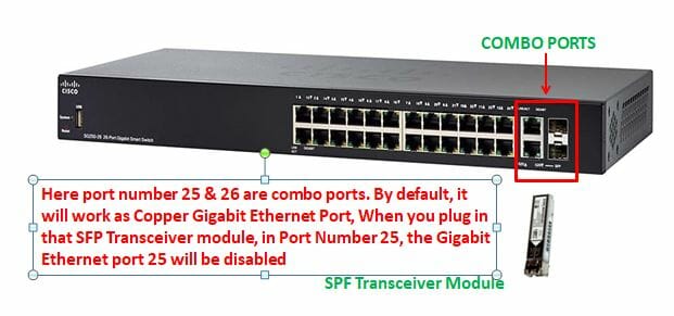
Connectivity:
A switch may have Fast Ethernet, Gigabit Ethernet, 10 Gigabyte Copper, or a SFP module for fiber. Many of them comes with combo port. Like I have shown in figure, there are 24 Gigabit Ethernet ports with 2 additional ports. You may use them as Gigabit Ethernet port with a UTP wire with RJ-45 connector. Once you plug in the SPF transceiver module for fiber, the corresponding copper port will be disabled.
Router
A router is the layer 3 device, which works in the Network layer and forwards the packet based on the IP address. It is responsible for forwarding the packet based on the destination address via the shortest route. Each Interface of the router is connected to different Networks.
Like I already illustrated earlier a layer 2 broadcast frame does not go beyond the router. IP address around the globe is unique and hence the router in the public domain can find the exact destination network for any valid address.
The router may be as common as one used in the home or small office Internet connection as a DSL/ADSL Router. More powerful routers are used by ISP’s as core router network. The core routers are generally connected in mesh topology between the prominent cities. Business and enterprise networks also use powerful and sophisticated routers.
It has connectivity for Ethernet, at all speeds and variants (Ethernet, FastEthernet, GigabitEthernet & 10 Gigabit Ethernet) depending upon the model. Besides, a router may have E1/T1 connectivity, Serial ports, SFP ports, ISDN BRI/PRI ports, etc. For configuration of a router, the Console port is always available since it does not comes in Plug and play condition. A router must be configured before putting it into use.
A router may share the network topology, connection status, reachability of neighboring networks with routers. For this purpose, various routing protocols are used.
Whenever a packet leaves the local network, it must be through a router. The Gateway of all networks is the IP of the router interface.
MODEM
MODEM is a short form for MODulation DEModulation. The modem is a device that converts Digital data into Analog at the time of Transmission and Analog to Digital at the time of reception. It has a long history of evolution, right from the acoustic modem to different standards from time to time.
The widely used for home or small office users is DSL (Digital Subscriber Line) Modem. The limit of last-mile copper is always there, as the long copper line is prone to noise. Most of the ISP’s terminate the OFC line in customer premises or nearby locations to minimize the length of last-mile copper. Alternately a direct FOC(Fiber Optics cable) may also be terminated using ONT (Optical Network Terminal).
There is one more variant for DSL for home users, i.e. ADSL (Asymmetric DSL) where download speed is kept high and upload speed has some restriction. Since the home users have more download traffics than upload, hence it is designed to utilize full efficiency of cable bandwidth.
All those modems we see now are a combination of various devices. Besides the basic Modem functionality, they serve as Broadband Router, Basic Firewall, DNS cache, Web Server, etc.
Gateway
Gateway is a type of Network Device which allows traffic from one discrete network to the other. It can operate in any layer of OSI layer depending upon its function, configuration, and implementation. It may be a piece of Network hardware or a complex combination of one or more devices.
A Network Gateway can allow communication between two separate communication systems with completely different Standard. Network Gateway is called protocol translators. For example, a gateway can be implemented to communicate between a circuit-switched network like ISDN with a packet-switched network like TCP/IP.
It is the entry and exit point in any network and all data should go through this.
For a LAN using the Internet, the Broadband Modem is referred to as a gateway.
Hope you enjoyed the topic. Please don’t forget to comment, if you have any query, suggestion, or feedback.
Take a Quiz on this topic :
Take another Quiz:
Share it with your friends from the share button below .