When you switch focus from a stand-alone computer to a computer network, there are two major elements, besides the Computers itself. First, one is Networking devices or Hardware, and the second is transmission media. Network devices are one that takes the packets forwarding decisions based on several protocols and algorithms. Whereas, the transmission media are responsible for the actual flow of bits from one device to another.
Various types of network media for establishment of a network are used. They are mainly as mentioned below:
- Coaxial Cable
- Twisted Pair Cable
- Glass Media
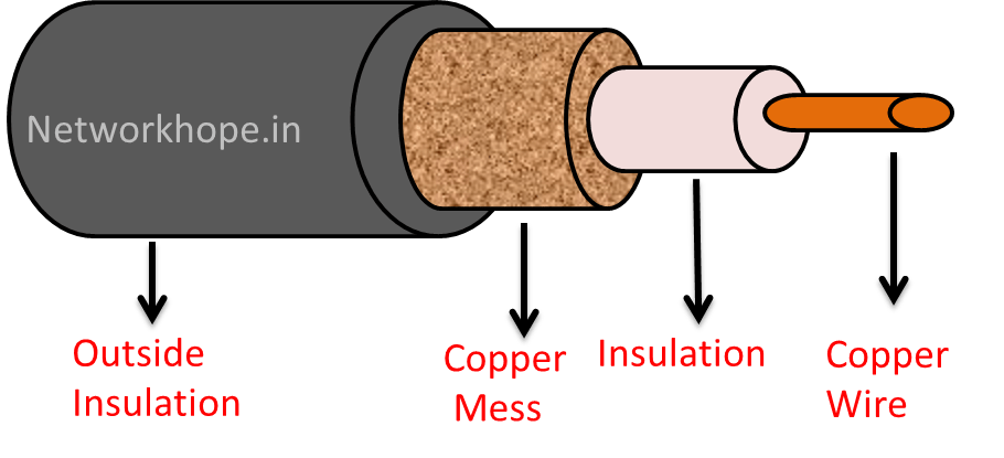
Transmission media types: Coaxial cable
Coaxial cable also is known as Coax is comprised of two concentric conductors separated by an insulator material. The inner conductor is generally a copper wire, insulation is called dielectric media and surrounding it is a copper mesh. Its called coaxial since both the conductor is on the same axis.
The outermost layer is a plastic sheath for protection. The dielectric is generally a solid polythene layer or a Teflon material.
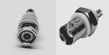
It is connected by BNC connector at the ends.
Coaxial cable was used in original Ethernet LAN networks as ThinNet and ThickNet. For details you may refer to Bus Topolgy in this blog.
Twisted pair cable
Twisted pairs are nothing but a bunch of twisted insulated conductors. There are various standards, names, designs, bandwidth limits, and overall speed limit depending upon the design. In a standard UTP cable, there are 4 pairs of twisted cable. They are probably the most common and affordable type of transmission media.
They are twisted simply to reduce the cross-talk. This is akin to transposition techniques used in an earlier telephone line by crossing the conductors after a few poles. Another important noise canceling approach is shielding them by a braided mesh encircling it.
Well, there is always a trade-off between the performance and the cost. So,due to reasonably good performance at an affordable price, UTP cables are the most preferred ones in LAN so far.
Types of twisted pair cable
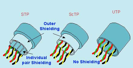
There are two types of Twisted pair- Shielded Twisted pair (STP), and Un-Shielded twisted pair (UTP). Shielded again have one more category, i.e. ScTP (Screened twisted pair).
The basic difference is STP has a shielding in each pair of conductor, as well as overall shielding at outside. ScTP is somewhat economical which lacks in individual pair of conductor’s shielding but provides an overall shielding at outer dia. UTP, as it’s name implies, is an un-shielded twisted pair comprising of 4 pair of cables .
The connectors at the ends are known as RJ-45, with an 8 pin connection. There is a color code, of course, so as to standardize the wiring.
UTP is most economic, widely used and convenient for a LAN with a 100 Mtr segment.
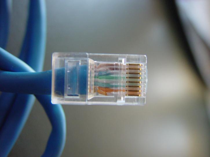
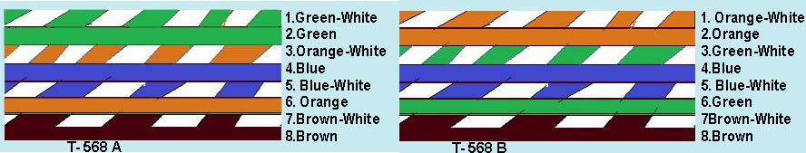
In the Figure above, the pin at bottom is Pin 1 and that in the top is pin 8. Hold the connector with notch downwards and metal pin side facing you. The extreme left is Pin 1. The image below the table shows the color code.
Twisted Copper Wire: Category Table
The history, performance of Twisted pair and their application cable is listed in following table. The maximum length of each segment is 100 Mtr for twisted cables.
| Category | Shielding | Maximum Transmission Speed at 100 Mtr | Maximum Bandwidth | Application |
| Cat 1 | Un-shielded | 1 Mbps | — | Old Telephone Cable |
| Cat 2 | Un-shielded | Upto 4 Mbps | — | Token Ring |
| Cat 3 | Un-shielded | 10 Mbps | 16 Mhz | Token Ring, 10BaseT Ethernet |
| Cat 4 | Un-shielded | 16 Mbps | 20 MHz | Token Ring |
| Cat 5 | Un-shielded | 10/100 Mbps | 100 Mhz | Ethernet, Fast Ethernet, Token Ring |
| Cat 5e | Un-shielded | 1 Gbps | 100 Mhz | Ethernet, Fast Ethernet, Gigabyte Ethernet |
| Cat 6 | Shielded/ Unshielded | 1 Gbps, 10 Gbps* | 250 MHz | Gigabyte Ethernet,*10 Gbps (up to 55 Mtrs) |
| Cat 6a | Shielded | 10 Gbps | 500 MHz | 10 Gbps Ethernet |
| Cat 7 | Shielded | 10 Gbps, 40 Gbps* 50 Mtr, 100 Gbps* 15 Mtr | 600 MHz | **GigaGate 45 connector in place of RJ-45 |
The RJ-45 Color code.
The Glass media: Optical Fibre cable
In this technology Glass or Plastic fibers are used as transmission media, where the light wave travels. An OFC (Optical Fiber Cable) consists of several tiny threads like cable (diameter of in terms of 100 microns or micrometer) bunched together and packed as a single tube.
OFC has certain advantages over a traditional electrical conductor:-
- The Bandwidth is very high, which means they can carry a large amount of data.
- They are free from Electra Magnetic Interference, hence no noise and cross-talk due to EMI. As a result, they can carry data for longer distances.
- They are not modulated in any analog carrier signal, rather they are converted from electrical signal to corresponding light signal and vice-versa.
- They cannot be tapped as easily as the electrical signals, so they are more secure.
Besides the advantages, there are certain disadvantages of OFC as well:-
- Expensive at initial set up.
- They are delicate, prone to damage, so it’s difficult to handle them.
- They are very thin, and needs special equipment (Splicing Machine) for joining them (Splicing).
- Needs a trained professional for splicing.
- They may be hazardous too for the person if it is not handled properly.
Principle of OFC
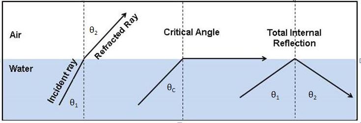
OFC Works in the principle of Total Internal Reflection. When light is traveling from denser medium (having high refractive index) to rarer medium (e.g. light traveling from water to air), the refracted wave tilts away from the normal, or the angle of refraction is greater than the angle of incidence. If we keep on increasing the angle of incidence, the angle of refraction also increases. At a certain point, the angle of refraction becomes 90 degrees or you may say the light refracts along the surface of the denser medium. That angle of incidence is called the critical angle.
Total internal reflection says that when the light is traveling from denser to a rarer medium if the angle of incidence is greater than the Critical angle, there will be no refraction, rather it will reflect to the same denser medium.
Construction of Optical Fibre cable
Fiber optics cable consists of two layers with a different refractive index. The internal layer is core and the cladding layer surrounds it. The coating is for protection purposes only and has no role in the transmission of light waves. You should remove the coating of OFC before splicing it..
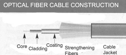
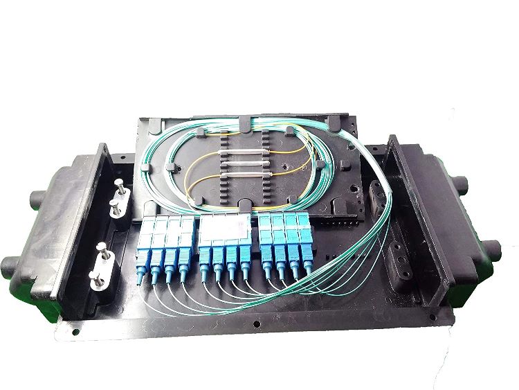
Several coated fibers are then bunched together and added with a layer of protective sheath and jackets. The protective elements depend on the design based on the use of these fibers. Fiber designed for indoor has different standards than one designed for outdoor use. Single-core fibers are also available in forms of pigtail connection, OFC patch cables, etc.
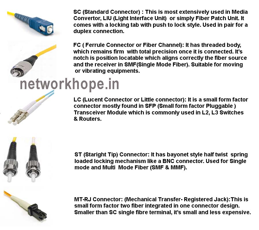
The connectors are different for different interfaces. The image below shows a few important types of OFC connectors.
Hope you liked the topic. Please comment your suggestions on the comment section below.
Contact me through the comments here or the contact form. We never display your email ID in comment.
Please Don’t forget to share it with your friends, from share button below.
Take a Quiz of this topic :