In continuation of my last tutorial on VLAN, let’s now proceed further to VLAN Configuration. I am using the Cisco packet tracer to configure VLAN on Cisco switches. I will cover this article in several blogs, i.e., Configure VLAN in Switches, Router on a stick, and VTP switch configuration. Stay connected to Network Hope for the latest blog. You may follow social links of Network Hope so that you don’t miss an update.
Basic VLAN Configuration
Let’s start from scratch with the configuration in a single switch. Let us focus on how to set-up the port-based VLAN in the Cisco switch. The steps of the VLAN configuration is accomplished in the following sequence.
- Create VLAN
- Give VLAN a name
- Add switch-ports to VLAN
- Assign an IP address to VLAN
The following diagram displays the outline for the VLAN configuration in a single switch. I have chosen the Cisco 2960 switch, which comprises of 24 Fast Ethernet Ports and 2 Gigabit Ethernet ports. You can check the device configuration in the tooltip by pointing the mouse on the device for a while.
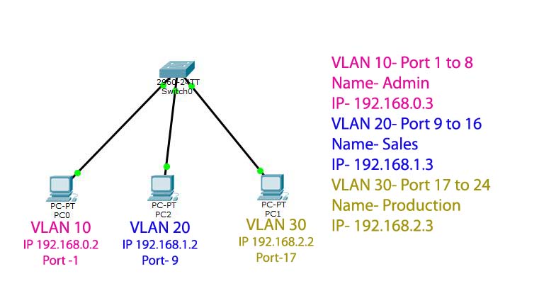
We will create three broadcast domain in the switch, VLAN 10, 20, and 30. The port assignment to the VLAN are Fast Ethernet ports 1-8, 9-16, and 17-24 in VLAN 10,20, and 30, respectively. The IP addresses of the PC and the VLAN are mentioned in the above image. VLAN 10 uses IP address pool 192.168.0.0/24, VLAN 20 has IP address 192.168.1.0/24, and VLAN 30 has the address 192.168.2.0/24. PC0 is connected to the switchport-1, PC1 to the switchport 9, and PC2 to the switchport 17. So, all three PCs are in different VLANs. You may connect more than one PC in every VLAN to check the interconnection. All the PCs connected through the ports 1-8 will be in VLAN 10, and so on for other VLANs.
Step by step configuration
In the beginning, assign IP addresses to all PCs. I have already covered IP assigning of PC in an earlier tutorial, you may check it from this link. Double click on the PC, go to the Desktop tab, then you will find the IP Configuration link at the top left of the wizard. Assign IP to the PCs, as stated in the above sketch. You may assign any IP address in the given range else you may plan your IP addresses by yourself. For any query about the IP addresses, refer to the blogs on IP address, and Classless IP.
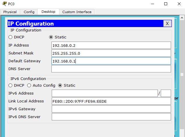
See the IP configuration in the first PC (PC0) in the above picture. The gateway IP is optional so far, as you have no link to an external network. The significance of the Gateway IP will be relevant only after adding a Layer-3 device. Let it be there for the time being. Configure the IP addresses in all PCs similarly. The gateway for VLAN 10 is 192.168.0.1, for VLAN 20 is 192.168.1.1, and 192.168.2.1 for VLAN 30.
Configure the Switch
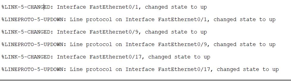
Now, open the CLI console by double-clicking on the switch. You should see something like the following figure. The switch ports connected to the PCs will display a UP status message. In my case, FE 0/1, 0/9, and 0/17 are connected hence display the message as shown.
Note that assigning a name and IP address to VLAN is not mandatory for communication between the hosts in the same VLAN. The hosts of the same VLAN can communicate without them. The only necessary component is the VLAN ID, a 12-bit field embedded along with the ethernet frame. VLAN name gives a meaningful indication to people managing the Network. An IP address is useful to access the device from a remote host. You can configure Telnet, SSH in the switch for remote logging with the IP address. There are many vendors, which provide a web-based interface for management as well.
Now type the following commands in the Switch, press Enter Key (↲) after each command:-
The following command will take you to Global Configuration mode. For more information on Basic commands, read this article. Also, assign an appropriate hostname to the switch. You can save the configuration by executing ‘write memory’ or ‘copy run start’ commands.
Switch>en
Switch#config t
Enter configuration commands, one per line.  End with CNTL/Z.
Switch(config)#hostname networkhope
Create VLAN
The following command will create VLAN 10. If the switch already has VLAN 10, then the same command will take you to (config-vlan)# prompt. From this prompt, you can name your VLAN.
networkhope(config)#vlan 10
networkhope(config-vlan)#name admin
networkhope(config-vlan)#exit
Assign IP address to VLAN
To assign an IP address to VLAN you have just created, enter the interface VLAN with the following command. From the Interface configuration menu (config-if)# prompt, you can assign an IP address to the VLAN in the given syntax.
networkhope(config)#interface vlan 10
networkhope(config-if)#
%LINK-5-CHANGED: Interface Vlan10, changed state to up

networkhope(config-if)#ip address 192.168.0.3 255.255.255.0
networkhope(config-if)#exit
Add switch port to VLAN
To add the switch port to an existing VLAN, you have to enter the interface setup by providing the interface ID. Switch port-1 is abbreviated as f0/1, switch port-2 as f0/2, and so on for other ports. Follow the syntax below for adding a single switch port to VLAN. First, enter the interface config mode, change the switch port mode to access, then allow the port to access the VLAN. The switchport is by default is in access mode; though if it is previously set to trunk mode, the command “switchport mode access” will revert it to the access mode.
networkhope(config)#interface f0/1
networkhope(config-if)#switchport mode access
networkhope(config-if)#switchport access vlan 10
networkhope(config-if)#
%LINEPROTO-5-UPDOWN: Line protocol on Interface Vlan10, changed state to up
The above command was used to add a single switch port to the VLAN. You can address a series of ports by the command interface range. The syntax is as given below.
networkhope(config)#interface range f0/1-8
networkhope(config-if-range)#switchport mode access
networkhope(config-if-range)#switchport access vlan 10
networkhope(config-if-range)#exit
Show VLAN
Use show VLAN command to view the VLAN statistics. You have to exit from Global config mode to the privilege mode to run the command.
networkhope(config)#exit
networkhope#
%SYS-5-CONFIG_I: Configured from console by console
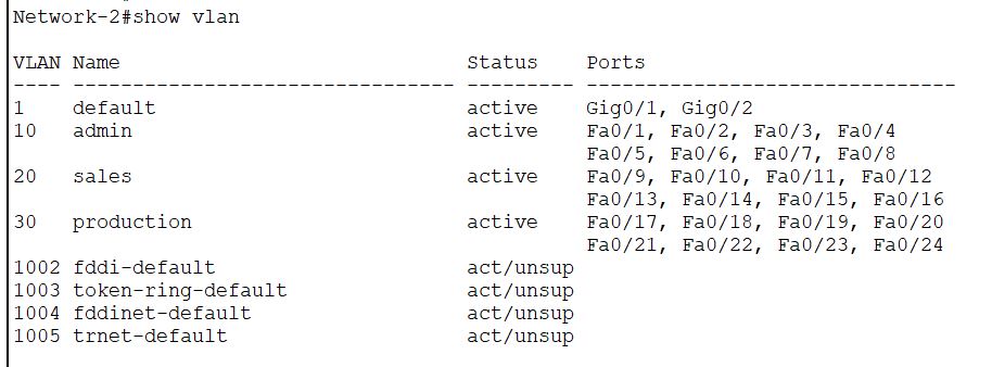
networkhope#show vlan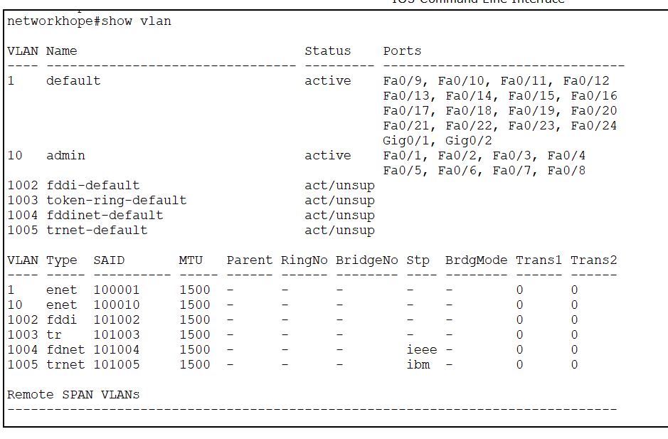
From the image above, you get all the information about the VLANs. The VLAN ID is 10, the name is admin, and the switch port association is from Fa0/1 to Fa0/8. You may also wish to check the IP address you have assigned to the VLAN 10. There are various methods to check the IP address of the VLAN. The easiest way is to keep the cursor on the device, and the tooltip will show you the IP address of all interfaces. But that doesn’t work in a real switch, mind it.
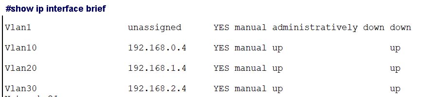
You can try the command “show interface vlan 10“, it will display various parameters of the VLAN including the IP address. You can also check “show ip interface brief” it will display all interfaces and their parameters in brief.
Configure All three VLANs
In the same way as VLAN 10 now create VLAN 20 and VLAN 30. Add the switch ports to VLANs and allocate the IP addresses, as shown in Figure 1. Follow the same procedure, replace the VLAN ID by corresponding numbers. Assign the names to the VLANs in the same way. If everything is correct, you should get the following result in the show vlan output.
Use the command “write memory” or “copy run start” to save the configuration. You should execute this command before switching OFF the device or closing the simulator. As ‘write’ and ‘copy’ both are the privilege mode commands, you should add a prefix “do” while running it from the global config or other elevated modes. You can also choose to exit from Global config mode to the privilege mode to execute the command without a ‘do’ prefix.
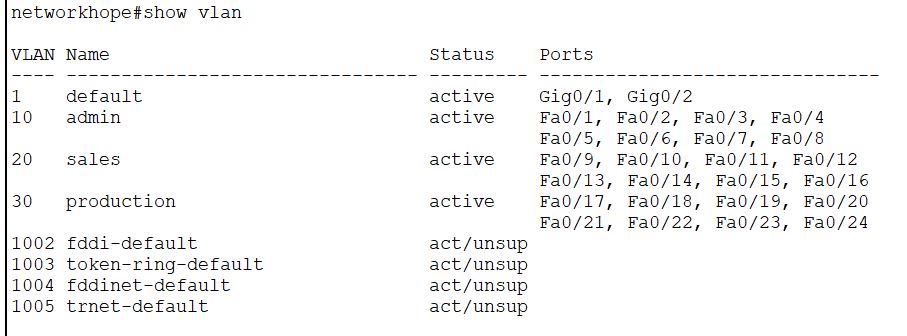
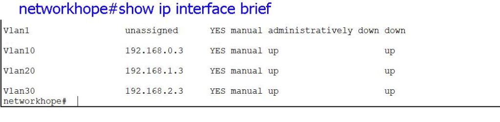
As you can see in the above images, all switch ports are allocated to the corresponding VLANs as per the outline in figure-1. Check the VLAN names and the IP addresses against each VLAN. Now, only two Gig ports are available with the default VLAN, i.e., VLAN 1.
Check VLAN
You may add some more PCs to the VLANs and assign IP addresses to them. Check each VLAN by pinging from one PC to another in the same VLAN. Alternately, you can ping the IP assigned to each VLANs from the corresponding PC. Now you have created three broadcast domains in the switch.
Let’s check the ping result from PC0 to VLAN 10. Double click on PC, from the Desktop tab, go to the Command Prompt, type the command ping 192.168.0.3, and hit the Enter button. The result should look like the following screenshot if everything is OK.
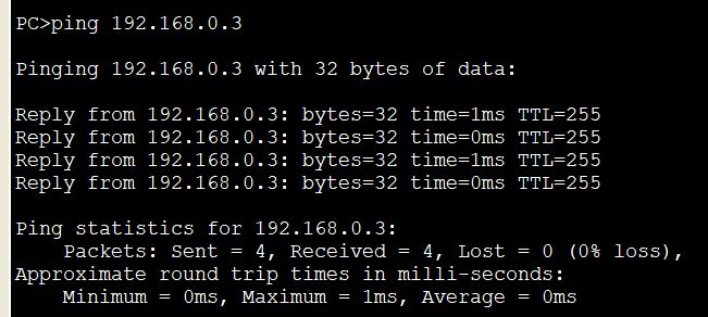
Check the ping result for other VLANs as well. If all the VLANs are pinging from the PC connected to them, we will proceed further to Configure the trunk port.
VLAN Configuration: the trunk Port
To configure the trunk port, add one more switch, as shown in the figure below. The configuration of Switch-2 is the same as that of Switch-1. Give a hostname to switch-2 different from that of switch-1. Make a list of IP addresses, switchport assignments, and other VLAN characteristics at the beginning. Here I have listed everything in the image below. I hope the sketch is sufficient enough to explain the outline.
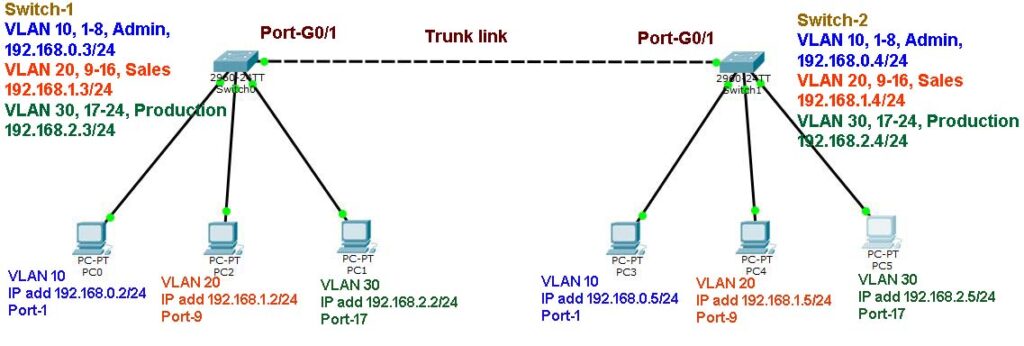
Connect switch-1 and switch-2 by a cross cable. Here the connection between them is through the switch ports G0/1 of each switch with a cross cable. Configure VLAN in switch-2 with the given parameters. Check the VLAN parameters like added switch ports, IP addresses, and VLAN names in switch-2. Also, assign IP addresses to the PCs. After configuration, it should look like the following screenshots.
Now, you may compare the VLAN parameters, with the image given above. The parameters as per the outline are configured on the switch-2.
Please note that it is not mandatory to assign the same ports to the VLANs in the switches. Here I am maintaining the symmetry for an easy understanding. For example, you may assign switch ports 1 to 8 in switch-1, and 1,3,5,7, and 8 in switch-2 in the same VLAN. You may also use the shortcuts of all commands, or use the Tab key to complete the command line. If you are not aware of those tricks, follow the instructions. We shall discuss those tips in the next chapter.
Trunk port configuration
If you have successfully done the configuration so far, let’s now configure the trunk ports.
networkhope(config)#interface gigabitEthernet 0/1
networkhope(config-if)#switchport mode trunk

networkhope(config-if)#
%LINEPROTO-5-UPDOWN: Line protocol on Interface GigabitEthernet0/1, changed state to down

networkhope(config-if)#exit
networkhope(config)#exit
networkhope#
%SYS-5-CONFIG_I: Configured from console by console

networkhope#write memory
Building configuration...
[OK]
Enter the interface config from global config mode; here, our interface is GigabitEthernet 0/1. Assign the switchport as a trunk port. Then exit from the interface config, then again exit from global config to the privilege mode. Save the configuration by write memory command.
Do the same trunk configuration in Switch-2. If you find any difficulty in language or explanation, you may comment below the post.
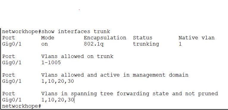
After configuring the trunk port in both switches you can verify the trunk line by the command:
show interface trunk
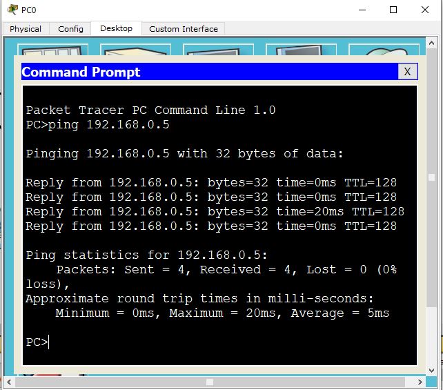
Now, you can check the VLAN functioning by pinging the remote host from the PC. Ping the PCs of the same VLAN from the left-hand side to the right-hand side or vice versa. The list of PC, VLAN, and the IP address is as under:
VLAN 10
Left-hand side PC – 192.168.0.2
Right-hand side PC- 192.168.0.5
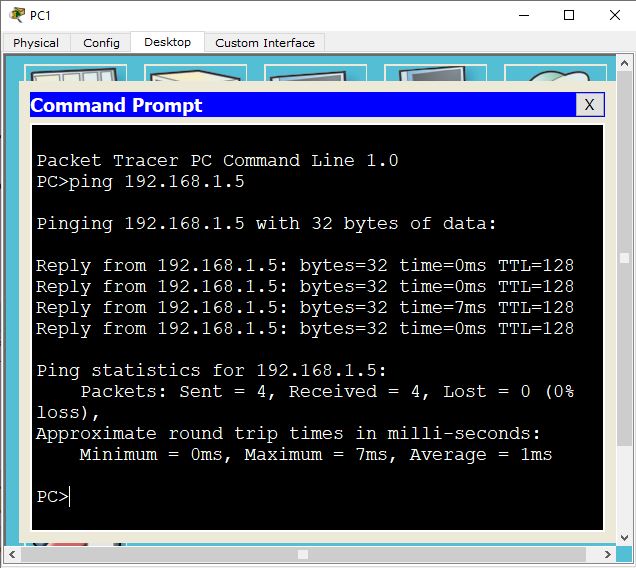
VLAN 20
Left-hand side PC – 192.168.1.2
Right-hand side PC- 192.168.1.5
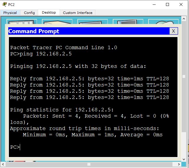
VLAN 30
Left-hand side PC – 192.168.2.2
Right-hand side PC- 192.168.2.5
In my case the ping results are as under:
How to remove VLAN from trunk list
You have seen that the trunk port in a switch allows all active VLANs by default. But in a router, you have to exclusively mention the VLAN ID to be allowed on a link. Also, in the switch, the encapsulation 802.1q is set, by default, but you should exclusively mention that in a router. We shall discuss that in my next blog Router in a stick. However, in a switch, you can remove the VLAN from the allowed list with the command, as shown below.Enter the trunk interface, execute the CLI command as shown, then save in memory.
networkhope(config)#interface g0/1

networkhope(config-if)#switchport trunk allowed vlan remove 10
networkhope(config-if)#do write memory
Building configuration...
[OK]
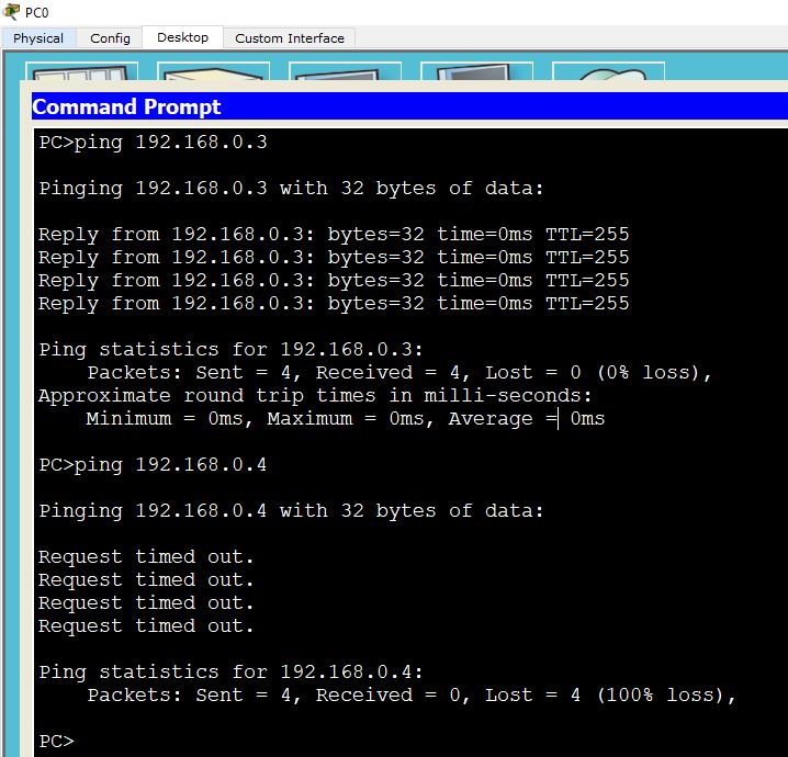
After removing the VLAN 10 from the trunk interface in the switch-1, the ping statistics are as below. Please note that the PC on the left-hand side is ab;e to ping the switch-1 VLAN IP address, i.e., 192.168.0.3, however it is not pinging the next switch IP, 192.168.0.4- through the trunk port.
To add the VLAN back to the trunk port, you need to run the command as shown below.
networkhope(config-if)#switchport trunk allowed vlan add 10
networkhope(config-if)#do write
Building configuration...
[OK]
Read more for VLAN routing with a Layer-3 device. Stay tuned to the updates of networkhope. Follow us on Facebook through the social link provided at the sidebar. You can share the article with the share widgets given at the top and bottom of the page.
Take a Quiz on this topic :