The ‘Router on a stick‘ is a method to transport multiple VLANs over a single router link. Also known as a one-armed router, it is the technique to allow inter-VLAN routing between the VLANs. In the last blogs, we have covered the VLAN configuration and trunk creation, and An overview of VLAN. Now, we shall try to introduce a Layer-3 device into the VLAN. With the help of the router, we can maintain the legacy of layer 2 VLAN, i.e., keeping the broadcast domain separate for each VLAN, and they will also be able to communicate as well when required.
For a video tutorial of the Inter VLAN Routing, refer to this video.
How Router in a stick works?
In router on a stick configuration, we divide an IP interface of the router to sub-interfaces. Each sub-interface carries specific VLAN traffic, you have to configure sub-interfaces as much as the number of VLANs. Here we shall configure three sub-interfaces on the Gigabit Ethernet link of the router. As we have seen in the last post, the switch trunk port by default carries the tagged frame of all active VLANs, but in the case of a router, we explicitly have to mention the VLAN association of each sub-interface. We also have to specify the encapsulation method. There are two possible methods of encapsulation in Ethernet, the ISL and IEEE 802.1q. For more information about frame tagging, refer to the blogs given in the links above.
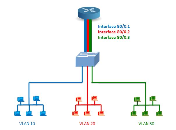
The above image illustrates the fundamental of the router on a stick. Please note the colors used in the diagram; each color represents a specific VLAN.
The different VLANs aggregates in a switch, those VLANS are further connected to an interface of the router. All the lines shown here are the trunk ports.
See the link between the switch and the router. It virtually accommodates three different paths in a link each path dedicated to a specific VLAN. The main interface G0/0 is sub-divided into the sub-interfaces as G0/0.1, G0/0.2, and G0/0.3. Each sub-interface is a dedicated channel for each VLAN.
Router or a Layer-3 switch?
One may choose a layer-3 switch for inter-VLAN routing. The layer-3 switch or a router- the choice depends on the purpose, services, and topology.
Of course, the layer-3 switch is not as versatile as a router, but it is more affordable. If you are using the network within proximity-a campus, or different floors of a building, etc. then the layer-3 switch is a better choice. They are specific in terms of function. Like they are designed to work in ethernet only, on the other hand, a router supports several protocols and standards.
When you have segments of the network in a geographically dispersed area, the traffic must go through a gateway like a router. Moreover, the router performs more sophisticated functions more efficiently like NAT, Access control, VPN management, etc. as required for a widespread network.
Router on a stick: The topology
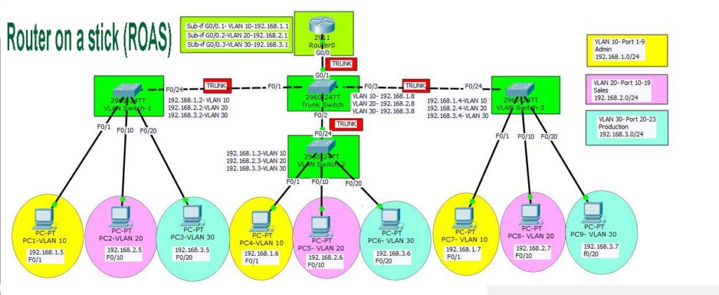
First, have a look at the sketch below, it’s a bit larger to view though. I suggest you open it in a different tab and observe it. For your convenience, I shall explain it to you in sequence. I hope, at the end of this article, you should be able to configure it with ease. The three VLAN PCs are in different colors, and the trunk ports are marked by red color in the figure.
I hope you may have studied the sketch so far. So, let’s start with how to set the router on a stick. Let me elaborate on the components used in the above images.
VLANs
- The first interface is VLAN 10, IP address block- 192.168,1.0/24, Name-Admin
- Second is the VLAN 20, IP address block- 192.168.2.0/24, Name- Sales
- And the third one is VLAN 30, IP address block- 192.168.3.0/24, Name- Production
Switches & Router
- On the Left-hand side of the diagram is VLAN Switch-1 having Switchports F0/1-F0/9- VLAN 10, F0/10-F0/19- VLAN 20, F0/20-F0/23- VLAN 30, G0/24- Trunk.
- At the middle bottom side, you may figure out the VLAN Switch-2, which has Switchports F0/1-F0/9- VLAN 10, F0/10-F0/19- VLAN 20, F0/20-F0/23- VLAN 30, and G0/24- Trunk.
- On the right-hand side, there is VLAN Switch-3, Switchports F0/1-F0/9- VLAN 10, F0/10-F0/19- VLAN 20, F0/20-F0/23- VLAN 30, G0/24- Trunk.
- The upper switch in the middle row is the Trunk Switch- F0/1 Trunk to VLAN Switch-1, F0/2 Trunk to VLAN Switch-2, F0/3 Trunk to VLAN Switch-3, G0/1- Trunk to Router0.
- At the top is the Router0 with sub-interfaces G0/0.1- VLAN 10, G0/0.2- VLAN 20, G0/0.3- VLAN 30, Encapsulation- 802.1Q (dot1q).
We may have configured all the trunk ports in the Gig interface, but we have only 2 Gig ports available in the switches. One Gig port of the Trunk Switch is connected with the router port for the perfect match. So, we don’t have many options in the trunk switch to configure all trunks with a Gigabit port.
With this much information about the topology and the outline, we are now well equipped to carry out the configuration part. So, let’s do it.
Step by step configuration
- Connect the devices as per the topology in the image. Mind the straight and cross cables used in the image. The switch to switch trunk links are joined by the cross cables.
- Assign the PCs with the IP addresses. Remember to specify the gateway IP address on each PC.
- Configure the VLANs in VLAN Switches- 1,2, & 3. Then assign switch-ports to VLAN as listed above. Also, configure the trunk Ports.
- Configure the VLAN in the trunk port. You don’t need to assign switch-ports here, as all the traffic to the switch comes through the trunk ports. But you must configure VLANs in this switch; otherwise, the device will not recognize the tagged frames of VLANs.
- Now the router should be configured to have three sub-interfaces, and each sub-if assigned to one VLAN.
Let’s execute the commands one by one.
Connect the devices
I hope you have already accomplished this step. Please, double-check the switch-ports where you are connecting the PCs. It should be in line with the VLAN configuration. Never go for an automatic cable selection while interconnecting the devices. Remember that similar devices are connected by a cross-cable and dissimilar devices by straight cable. However, the devices automatically detect the straight and cross cable nowadays, still, you should know it.
For example,
Switch to switch: cross-cable
Router to a switch, or a switch to host: straight cable
Router to router: cross-cable
(Exception- direct connection in a router to a host requires cross-cable.)
Assign the PCs with the IP addresses
Assigning an IP address to the PC is already covered in previous blogs. If you are unaware of the method, please follow this link. I will still suggest you prepare an IP chart so that you can avoid mess-up in the complex networks. Please remember the gateway IP of all VLANs. For VLAN 10, it is 192.168.1.1 for VLAN 20- 192.168.2.1 and VLAN 30- 192.168.3.1.
Configure the VLANs in VLAN Switches- 1,2, & 3
I will show you the configuration of VLAN switch-1, you may do it in the same manner in VLAN switch-2 & 3. Everything is the same except the IP address and VLAN name, change them accordingly.
Execute the following command to change the hostname. Do the same in other switches and routers as well.
Switch>en
Switch#config t
Enter configuration commands, one per line.  End with CNTL/Z.
Switch(config)#hostname VLAN-SWITCH-1
VLAN-SWITCH-1(config)#
Now create three VLANs one by one, let’s first see the command for VLAN 10. The explanation of the VLAN commands is in the previous blog; please refer to that for further information. The following is the syntax for creating a new VLAN, assigning an IP address to it, and adding the switch-ports to the VLAN.
VLAN-SWITCH-1(config)#vlan 10
VLAN-SWITCH-1(config-vlan)#name Admin
VLAN-SWITCH-1(config-vlan)#exit
VLAN-SWITCH-1(config)#interface vlan 10
VLAN-SWITCH-1(config-if)#
%LINK-5-CHANGED: Interface Vlan10, changed state to up

VLAN-SWITCH-1(config-if)#ip address 192.168.1.2 255.255.255.0
VLAN-SWITCH-1(config-if)#exit
VLAN-SWITCH-1(config)#interface range f0/1-9
VLAN-SWITCH-1(config-if-range)#switchport mode access
VLAN-SWITCH-1(config-if-range)#switchport access vlan 10
VLAN-SWITCH-1(config-if-range)#exit
Now create VLAN 20, assign IP address, and add switch-ports to the VLAN in the same way.
VLAN-SWITCH-1(config)#vlan 20
VLAN-SWITCH-1(config-vlan)#name Sales
VLAN-SWITCH-1(config-vlan)#exit
VLAN-SWITCH-1(config)#interface vlan 20
VLAN-SWITCH-1(config-if)#
%LINK-5-CHANGED: Interface Vlan20, changed state to up

VLAN-SWITCH-1(config-if)#ip address 192.168.2.2 255.255.255.0
VLAN-SWITCH-1(config-if)#exit
VLAN-SWITCH-1(config)#interface range f0/11-19
VLAN-SWITCH-1(config-if-range)#switchport mode access
VLAN-SWITCH-1(config-if-range)#switchport access vlan 20
VLAN-SWITCH-1(config-if-range)#exit
The last VLAN is VLAN 30, let’s configure it.
VLAN-SWITCH-1(config)#vlan 30
VLAN-SWITCH-1(config-vlan)#name Production
VLAN-SWITCH-1(config-vlan)#exit
VLAN-SWITCH-1(config)#interface vlan 30
VLAN-SWITCH-1(config-if)#
%LINK-5-CHANGED: Interface Vlan30, changed state to up
VLAN-SWITCH-1(config-if)#ip address 192.168.3.2 255.255.255.0
VLAN-SWITCH-1(config-if)#exit
VLAN-SWITCH-1(config)#interface range f0/20-23
VLAN-SWITCH-1(config-if-range)#switchport mode access
VLAN-SWITCH-1(config-if-range)#switchport access vlan 30
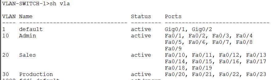
VLAN-SWITCH-1(config-if-range)#exitYou may like to check the VLANs by the show VLAN command.
Also, the IP addresses of VLANs can be checked by the command “show ip interface brief” . The result should display as:
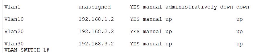
You can configure the VLAN-SWITCH-2 and the VLAN-SWITCH-3 in the same way. If you face any difficulty, you may comment at the bottom of the post with your query.
Configure the Trunk-Switch
You may have wondered why I have not configured the trunk ports in VLAN Switches so far. All three switches should have trunk ports at F0/24 port. The F0/24 ports of VLAN-Switch-1, 2, & 3 are connected to F0/1, F0/2, and F0/3 ports of the Trunk switch, respectively. Refer to the image above.
When you configure the trunk port at one switch, the other port connected to another end will automatically be configured. I will show you the screenshot, of how to identify the auto-configured switch-port. For example, if I configure the F0/1 port of the trunk switch as a trunk port, the other end i.e., F0/24 of the VLAN-SWITCH-1 will have an automatically configured trunk port.
Configure VLANs in the Trunk-Switch
First, you need to configure all three VLANs in the trunk switch as well. You may assign an IP address to VLANs if you need it for managing the device from remote. The IP address of the device also helps to troubleshoot the network. You may check the ping statistics in the case of a network error.
We will create VLANs, give a name to VLANs, then assign the IP addresses to the VLANs in this device. We won’t add any switch-port to the VLANs in this switch.
The VLAN configuration of the TRUNK-SWITCH is as under:
TRUNK-SWITCH(config)#vlan 10
TRUNK-SWITCH(config-vlan)#name Admin
TRUNK-SWITCH(config-vlan)#exit
TRUNK-SWITCH(config)#interface vlan 10
TRUNK-SWITCH(config-if)#
%LINK-5-CHANGED: Interface Vlan10, changed state to up

TRUNK-SWITCH(config-if)#ip address 192.168.1.8 255.255.255.0
TRUNK-SWITCH(config-if)#
TRUNK-SWITCH(config)#vlan 20
TRUNK-SWITCH(config-vlan)#name Sales
TRUNK-SWITCH(config-vlan)#exit
TRUNK-SWITCH(config)#interface vlan 20
TRUNK-SWITCH(config-if)#
%LINK-5-CHANGED: Interface Vlan20, changed state to up

TRUNK-SWITCH(config-if)#ip address 192.168.2.8 255.255.255.0
TRUNK-SWITCH(config-if)#
TRUNK-SWITCH(config)#vlan 30
TRUNK-SWITCH(config-vlan)#name Admin
TRUNK-SWITCH(config-vlan)#exit
TRUNK-SWITCH(config)#interface vlan 10
TRUNK-SWITCH(config-if)#
%LINK-5-CHANGED: Interface Vlan10, changed state to up
TRUNK-SWITCH(config-if)#ip address 192.168.1.8 255.255.255.0
TRUNK-SWITCH(config-if)#Configure the trunk ports in the Trunk-Switch
Now configure the trunk ports on TRUNK-SWITCH. There are four ports to be configured as the trunk in this device. You can address all of them together by the “interface range” command. The syntax is as given below; put a comma for the switch port, which is not adjacent to the previous group.
On execution, you will get messages of several lines of the addressed interfaces UP status.
TRUNK-SWITCH(config)#interface range f0/1-3, g0/1
TRUNK-SWITCH(config-if-range)#switchport mode trunk


TRUNK-SWITCH(config-if-range)#
%LINEPROTO-5-UPDOWN: Line protocol on Interface FastEthernet0/1, changed state to down

%LINEPROTO-5-UPDOWN: Line protocol on Interface FastEthernet0/1, changed state to up

%LINEPROTO-5-UPDOWN: Line protocol on Interface Vlan10, changed state to up

%LINEPROTO-5-UPDOWN: Line protocol on Interface Vlan20, changed state to up

%LINEPROTO-5-UPDOWN: Line protocol on Interface Vlan30, changed state to up

%LINEPROTO-5-UPDOWN: Line protocol on Interface FastEthernet0/2, changed state to down

%LINEPROTO-5-UPDOWN: Line protocol on Interface FastEthernet0/2, changed state to up

%LINEPROTO-5-UPDOWN: Line protocol on Interface FastEthernet0/3, changed state to down

%LINEPROTO-5-UPDOWN: Line protocol on Interface FastEthernet0/3, changed state to up

%LINEPROTO-5-UPDOWN: Line protocol on Interface GigabitEthernet0/1, changed state to down

%LINEPROTO-5-UPDOWN: Line protocol on Interface GigabitEthernet0/1, changed state to up
Once you have configured the trunk ports, check the trunk ports by the “show interfaces trunk” command, you should get the following result.
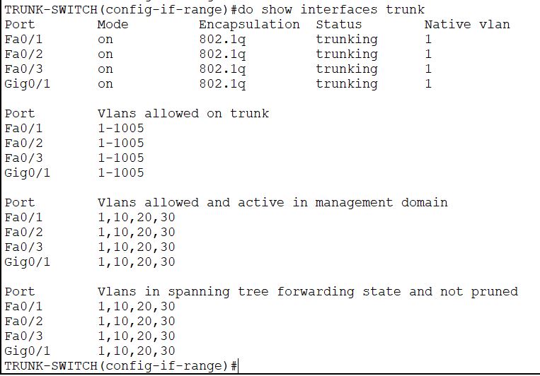
Please note that I have used a ‘do’ prefix before the command, as I have executed it from Interface Config mode. Also note down the Mode of the trunk, which shows the ‘on’ status, we will talk about later. Now you have verified the four trunk ports, which seems working fine.
Now also verify the trunk ports in VLAN-Switches, I will show you one of them. See the trunk port status of VLAN-SWITCH-1 in the image below.
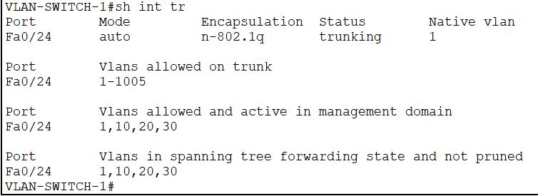
Yes, it shows that one port is in trunk mode, i.e., f0/24. I hope you remember that this switch-port is linked to the f0/1 of the trunk switch.
Have you noticed any difference in the status? See the mode here, it displays an ‘auto’ mode, unlike the earlier switch which showed an “on” status. It means the trunk port is configured automatically.
You can verify the trunk ports in VLAN-SWITCH-2, & 3 similarly.
With this setup, you can check the ping statistics of the network. All hosts should ping the host in the same VLAN. However, it will not ping the hosts in other VLANs and the Gateway. For that to happen, you need to configure the router.
Configure the router
The router, you should configure in the following steps:
- Configure Sub-interfaces: do in the same sequence.
- define the interface: interface G0/0.1
- Encapsulation and VLAN ID: encapsulation dot1q 10
- Assign IP address: ip address 192.168.1.1 255.255.255.0
- No Shut: no shut
Repeat the steps for all sub-interfaces, change the IP address and the VLAN ID accordingly.
2. Configure the Interface- no shut
The initial status of the router is as shown in the following image. All the interfaces are down, and no IP address is there. Now I will show you the configuration.
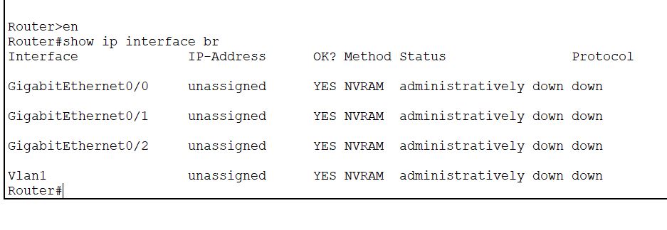
At first, assign a name to your router. The second line “no ip domain lookup” is given to ignore the typos during configuration. Else, it will try to resolve the erroneous command from the IP domain. In that case, you can abort it by pressing the SHIFT+CONTROL+6 buttons together.
Router#config t
Enter configuration commands, one per line.  End with CNTL/Z.
Router(config)#hostname ROUTER-1
ROUTER-1(config)#no ip domain lookup
ROUTER-1(config)#
Now, configure all three sub-interfaces one by one.
ROUTER-1(config)#interface g0/0.1
ROUTER-1(config-subif)#encapsulation d
ROUTER-1(config-subif)#encapsulation dot1Q 10
ROUTER-1(config-subif)#ip address 192.168.1.1 255.255.255.0
ROUTER-1(config-subif)#no shut
ROUTER-1(config-subif)#
ROUTER-1(config)#interface g0/0.2
ROUTER-1(config-subif)#encapsulation d
ROUTER-1(config-subif)#encapsulation dot1Q 20
ROUTER-1(config-subif)#ip address 192.168.2.1 255.255.255.0
ROUTER-1(config-subif)#no shut
ROUTER-1(config-subif)#ROUTER-1(config)#interface g0/0.3
ROUTER-1(config-subif)#encapsulation d
ROUTER-1(config-subif)#encapsulation dot1Q 30
ROUTER-1(config-subif)#ip address 192.168.3.1 255.255.255.0
ROUTER-1(config-subif)#no shut
ROUTER-1(config-subif)#Once you have configured the sub-if, now change the main interface to ON. The sub-interfaces will switch ON only after you enable the interface GigabitEthernet0/0.
ROUTER-1(config)#interface g0/0
ROUTER-1(config-if)#no shut

ROUTER-1(config-if)#
%LINK-5-CHANGED: Interface GigabitEthernet0/0, changed state to up

%LINEPROTO-5-UPDOWN: Line protocol on Interface GigabitEthernet0/0, changed state to up

%LINK-5-CHANGED: Interface GigabitEthernet0/0.1, changed state to up

%LINEPROTO-5-UPDOWN: Line protocol on Interface GigabitEthernet0/0.1, changed state to up

%LINK-5-CHANGED: Interface GigabitEthernet0/0.2, changed state to up

%LINEPROTO-5-UPDOWN: Line protocol on Interface GigabitEthernet0/0.2, changed state to up

%LINK-5-CHANGED: Interface GigabitEthernet0/0.3, changed state to up

%LINEPROTO-5-UPDOWN: Line protocol on Interface GigabitEthernet0/0.3, changed state to up
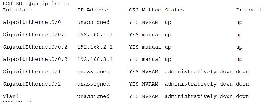
Verify the configuration by show ip int brief command now. The image is self-explanatory; I hope that I don’t need to explain it.
Verify the network
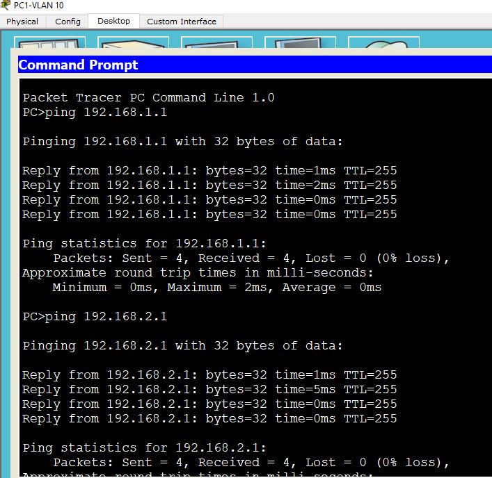
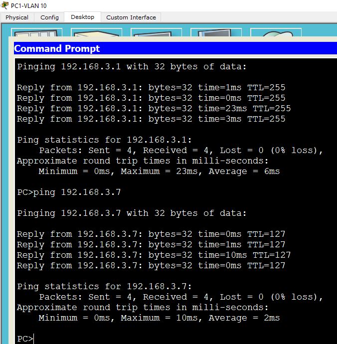
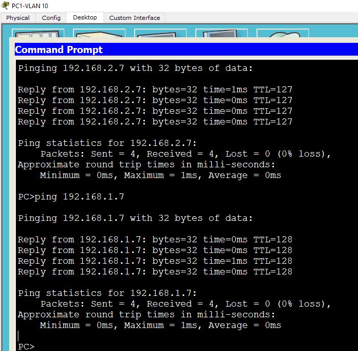
At this point, you should be able to ping any host from anywhere in your network. Please verify the installation by pinging. It may take a few minutes to populate the topology and start pinging. In the case of difficulty, you may try pinging step-by-step to troubleshoot. First, ping the VLAN-Switch you are connected to, then ping the Trunk-Switch, then the gateway router. Once you are able to ping the gateway from all VLANs, the inter-VLAN routing will function. I will show you the pinging statistic from PC-1-VLAN-10.
Configure Inter VLAN routing with a layer 3 switch
We have completed the configuration of inter-VLAN routing using a router. If you want to use a Layer 3 switch, it’s pretty easy. Have a look at the image below. Then we will see how to configure it.
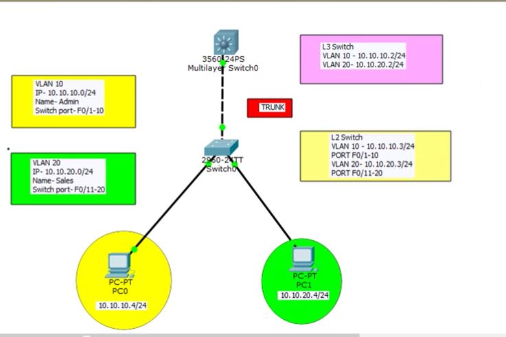
It shows a simple topology with two VLANs. The IP assignment for VLAN 10 is 10.10.10.0/24, and that for VLAN 20 is 10.10.20.0/24. The hosts are connected to an L-2 switch in access mode, and the L-2 switch is connected to a multilayer switch in trunk mode. PC0 is connected to switch port F0/1, PC1 is connected to F0/11, and the L-2 switch is connected through G0/1 to the G0/1 port of L-3 switch. Port assignment for VLAN 10 is F0/1-F0/10, and that for VLAN 20 is F0/11-F0/20.
I hope that you will be able to set up the connection. Now do the following in sequence.
- Assign IP addresses to the PCs, configure gateway IP as the IP of the L-3 switch.
- Configure VLAN in the L-2 switch, add ports to the VLAN and assign IP to each VLAN.
- Configure the trunk port in the L-2 switch.
- Verify the VLAN and trunk port.
- In the L-3 switch, check the trunk port, it should automatically be created.
- Create VLANs in the L-3 switch, assign the IP address. Note that the IP assigned to the VLAN in the L-3 switch should be the gateway IP of the PC of respective VLAN.
- Verify the VLANs.
- So far, the commands have been discussed earlier. Now the important command for routing purposes is ip routing. Execute the command from the Global config mode: ip routing. Then save everything, ping VLAN 20 from VLAN 10 and vice versa. It should now work.
Thank you for reading it. Here we finished the configuration of VLAN and the Router on a stick. I hope this article will be helpful for the seekers. Keep in touch with the Network Hope for further updates.
Take a Quiz on this topic :