
ISO OSI Basic reference model: Introduction
ISO OSI basic reference model was first published by the International Organization for Standardization (ISO) in 1984. The open standard was then published as ISO 7498. The revision and corrigenda followed it quite a few times, the current revision being ISO/IEC 7498-1, 1994. The Open Systems Interconnection – Basic Reference Model: The basic model also published as ITU-T (CCITT earlier) X.200: 1988 (Superseded) & 1994 standard.
(IEC- International Electrotechnical Commission).
The OSI model is not a protocol, but it is the foundation for designing the protocols. It is a layered framework that provides a platform for designing robust, flexible, and interoperable network architectures.
The OSI reference model aims to provide interoperability between various communication systems with the help of standard communication protocols. It’s an open model that partitions the communication approach in a layered architecture.
The Open Systems Interconnection 7 layer architecture is a hypothetical design that defines and standardizes the communication features of the data communication system.
Layered Architecture
The seven layers of the ISO OSI basic model are as follows:-
The recommendation X.200 defines seven layers, named as layer 1 to layer 7. The lowest level is level 1, and layer 7 is the highest level.
| Layer | Name | Important protocols used in equivalent layers in the practical implementation of the OSI model |
| Layer 1 | Physical Layer | IEEE 802.3 Physical layer, USB physical layer, IEEE 802.11 physical layer, DSL, ISDN, T1/E1, |
| Layer 2 | Data Link layer | ARP, CHAP, FDDI, Frame relay, 802.11 Wi-Fi, IEEE 802.16 Wimax, PPP, L2TP, etc. |
| Layer 3 | Network Layer | Internet Protocol (IP), ICMP, ARP, RIP, OSPF, NAT, IPSec, etc. |
| Layer 4 | Transport Layer | TCP, UDP, AH & ESP of IPSec, iSCSI, NetBIOS, etc. |
| Layer 5 | Session Layer | RPC, PAP, NetBIOS, NetBEUI, RTCP, etc. |
| Layer 6 | Presentation Layer | JPEG, MIDI, MPEG, TIFF, GIF, ASCII, EBCDIC, etc. |
| Layer 7 | Application Layer | http, https, DNS, POP-3, SMTP, FTP, SNMP, etc. |
For the learners, they may devise any method to remember the layer names. Or you may memorize layers 7 to 1 chronologically with the phrase “A Public Switched Telephone Network & Digital Phones”. It has got no meaning, though it’s easy to remember.
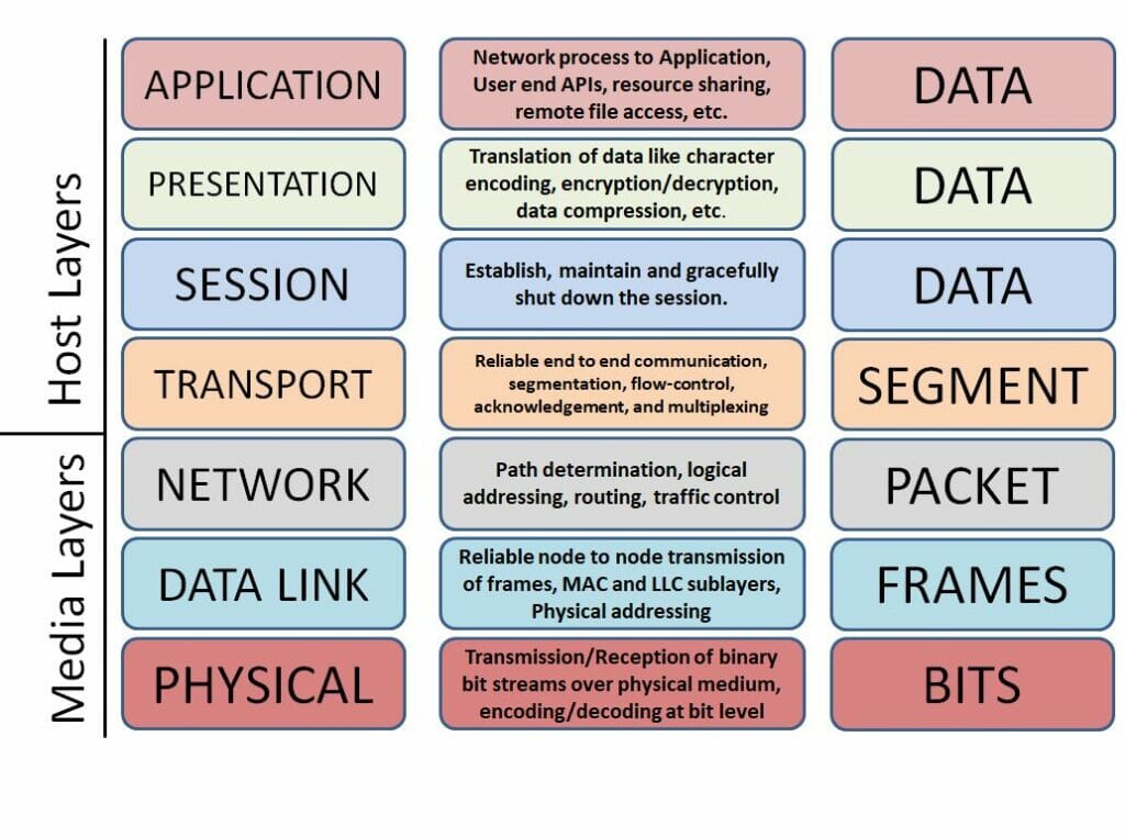
The following figure shows the functions of each layer in brief. The top four layers, called the host layers, as the function of these layers is performed exclusively between participating hosts.
The bottom three layers are responsible for delivering the data from source host to destination host are called the media layers. Most of the functions of these three layers are performed by the intermediate devices.
Within one machine, each layer calls upon the services of the layer just below it. Layer 3, for instance, uses the services provided by layer 2 and provides services for layer 4.
Between machines, any layer in the source host communicates with the same layer of the destination host. This communication is governed by a pre-decided series of rules and conventions called protocols.
Layer to layer data flow
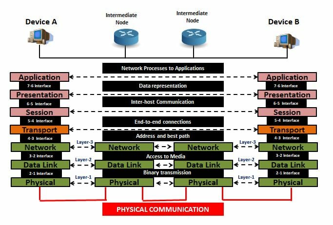
In the figure below, you can see that host A sends a message to host B (through intermediate nodes). At station A, the message flows down from layer 7 to layer 1. The entire message along the headers is converted to a raw data stream at layer 1 of station A. The raw data now travels to the receiving end through intermediate nodes. At station B, which is the receiving side, the message moves up from layer 1 to layer 7.
The movement of data through the layers downwards at sending stations and upwards at the receiving station is made possible by the interfaces between the adjacent layers. Each interface is well defined in terms of its services and features. It provides the modular construction of the Architecture. The upper layer has nothing to do with the implementation of lower layers, as long as they render the service to the upper layers. For example, the packet sent by the Network layer to lower layers has a condition that the packet should reach in the same state to the next network layer. Whatever the standard or protocol being used at Data Link and Physical layer is non of its concern as long as the packet reaches in its original form.
Though the flow of data is in a vertical direction, the practical implementation of the OSI layer seems to have communication horizontally with the same layer of another end.
The sub-groups of OSI layer
We may consider The seven layers of the OSI model comprising of three subgroups.
The three sub-groups are the user support layer or the upper three layers, the network support layer or the lower three layers, and the transport layer as an interface between those two sub-groups.
The network support layer comprising of layer 1, 2, and 3, deals with the physical aspects of transferring data from sender to receiver. This sub-group is concerned with physical connections, electrical specifications, transport time, physical addressing, etc. The user support layer comprising of layer 5, 6, and 7, deals with the interoperability between the different software systems. The transport layer links the two sub-groups and ensures the data sent by the lower sub-group is in the form usable by the upper sub-group.
The upper layers of the OSI model are mostly implemented by software, whereas the lower may have a combination of hardware and software. Exclusively the physical layer is mostly hardware.
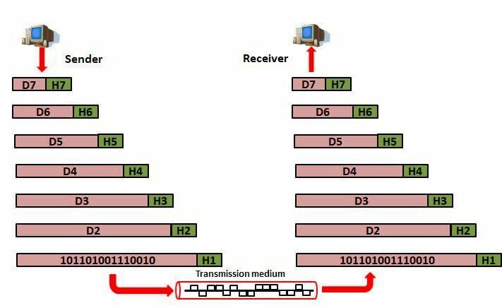
The above figure gives an overview of OSI layer data communication. D7, D6, etc. are the data at layer 7, 6, and so on. The data starts from sender station layer 7, i.e., D7. Each layer will add a header to the data received from the upper layer. Finally, it passes through the physical layer as bitstreams to the physical layer of the receiving station.
Upon reception, the data moves to upward layers. At each layer, the corresponding headers are removed. All the layer performs their respective roles. By the time it reaches layer 7, it comes in its original form sent by the application layer.
Another feature of layered architecture in the OSI reference model is the encapsulation. The header of the upper layer is treated as the data at the lower layer. The lower layer cannot distinguish between the data and the header of the upper layer. For example, the D7+H7,(i.e., Data+Header) at layer 7 is treated as D6 at the 6th layer. It just encapsulates the complete unit received from the upper layer and adds its header. The image illustrates the encapsulation done by each layer.
The data unit at any layer is called the Protocol Data Unit (PDU). The N layer or the topmost layer sends its PDU to the N-1 layer. The PDU of the N layer serves as SDU (Service Data Unit) at the next lower layer, i.e., the N-1 layer. N-1 layer, in turn, adds its header (might be footer too) to the SDU. Now, this becomes the PDU of the N-1 layer.
Similarly, the PDU at the N-1 layer serves as the SDU to the N-2 layer. It again encapsulates it with the requisite header then it becomes PDU at the N-2 layer. The process continues until the lowermost layer.
At the receiver, the data passes from the lower to the upper layer. Each layer extracts the header and footer and transfers it to the next upper layer until the topmost layer.
Layer 1: The Physical layer
This is the first or the lowest layer in the ISO OSI reference model. This layer is responsible for converting digital raw bits into electrical, optical, or the radio signals which best suits the transmission media and moving each bit from one node to the other.
This layer defines various physical characteristics like shape and size of interface connectors, voltage levels, the timing of voltage change, transmission rate, the maximum distance of transmission, modulation and access methods, etc. The layout of pins and connectors, transmission mode like a simplex, half-duplex, duplex, signal time, frequency of RF signals in Wireless media are performed by the Physical layer.
The layer interfaces the Media Access control (MAC) sub-layer of the Data Link layer and supports the higher layers to communicate through the media. The aim of this layer is to provide bit-by-bit delivery. So as to do this, it standardizes the various electrical, mechanical, radio, and optical characteristics of the interfaces depending upon the transmission media.
Apart from this, the bit synchronization in serial communication and start and stop bit in Asynchronous communication, etc. are the physical layer specifications. Bit-level error correction by applying the Forward error correction method is done by this layer. The physical layer also defines the topology of the network.
To summarize the functions of physical layer:
- Physical characteristics of the interfaces & media
- Representation of bits
- Data rate/ Transmission rate
- Synchronization of bits
- Line configuration- Point to point/ Multipoint
- Physical Topology
- Transmission Mode- Simplex/half-duplex/ full-deplex.
Layer 2: The Data Link Layer
The second layer of the ISO OSI Basic reference model, the data link layer (Layer 2) is responsible for the node to node data transfer. It transforms the raw data from the physical layer to a reliable link and makes the physical layer look error-free to the upper layers. It detects and corrects errors occurred in the physical layer.
This layer defines the link establishing protocols to establish and terminate the node-to-node link and also manages the flow control between them. It divides the packet received from the network layer into smaller units called frames.
It provides physical addressing to the frames by adding the MAC addresses. A data link header added to each frame consists of MAC addresses of the source and destination address belonging to the same network segment. If the destination does not belong to the network, it will add the MAC address of the configured gateway as the destination.
Access control if the multiple devices are using the same link, to determine the control over the link by the device at a given time.
MAC and LLC Sublayers
Datalink layer has two sublayers- Media Access Control (MAC) sublayer and the Logical Link Control (LLC) sublayer.
The MAC sublayer interfaces with the physical layer and is responsible for controlling the hardware interacting with optical, wired, or wireless transmission medium. Its main functions are encapsulation, physical addressing, collision detection, error correction, retransmission, control of access to physical media, etc.
The LLC, upper sublayer of layer 2, acts as an interface between the Network layer and the MAC sublayer. It has multiplexing capability, which helps accomodating multiple protocols at the Network layer (IP, IPX, DECnet, etc.) and transmitted over the same physical medium. It can also provide node-to-node flow control and error correction, which is optionally used by some protocols.
We can summarize the functions as:-
- Framing
- Physical addressing
- Flow control
- Error control
- Multiplexing of multiple protocols at a higher layer
- Access control of channel by the devices
Layer 3: The Network Layer
The network layer or the third layer of the ISO OSI Basic reference model is mainly responsible for logical addressing, packet forwarding, routing across multiple networks. It provides source-to-destination delivery of a packet.
Unlike the data link layer, which facilitates node-to-node delivery within a network, the network layer provides delivery from source-to-destination across the network. If two systems exist in the same network, there is no need for an intermediary third layer. However, if they are in different network segments, there is a need for a third layer device to ensure packet delivery from source to destination.
The functions of the layer include:
Connectionless delivery: As in the IP address of the TCP/IP protocol suite where data packets travel from source to destination without the acknowledgment from the recipient.
Host addressing: The logical addressing of the host on the Internet is the IP address. Other addressing schemes are IPX (Novell Networks proprietary Internet Packet eXchange protocol), SNA (IBM’s old protocol System Network Architecture), or DECnet( A protocol developed by Digital Network Corporation). The IP being open and one of the constituents of the TCP/IP protocol suite is well known and the widely accepted one.
Packet forwarding/ Routing: In the World Wide Web, WAN, etc., there are several networks, divided into subnetworks, connected by various links. The group of dedicated devices called the routers/gateways forward the packet to the destination using the IP address in such a network.
The well-known protocols of this layer are the IPv4/IPv6, ICMP (Internet Control Message Protocol), IGMP (Internet Group Management Protocol), and the various routing protocols like OSPF, RIP, EIGRP, etc.
Layer 4: The transport Layer
The transport layer, the fourth layer of the ISO OSI reference model, serves as process-to-process delivery of complete information. The application program running on the end device is a process. In the previous section, we saw that the network layer renders the source-to-destination delivery. However, the network layer is not responsible for the delivery of a complete message from the source-to-destination. It treats each packet as an independent object and delivers them from source-to-destination.
The transport layer, on the other hand, ensures the sequencing of datagrams (small chunks of data at the transport layer) at the sender side and rearrange them at the receiver side. It also performs flow control and error correction at the source-to-destination level.
The transport layer divides the data received from the upper layers into small, manageable chunks. This function is known as segmentation. It also reassembles them back at the receiver end. The layer is responsible for providing acknowledgment of the successful data transmission and ensures a connection-oriented, reliable communication.
The main functions of the transport layer are as under:-
Port addressing– Also called the service point addressing is a mechanism that assigns a unique port number to each process. The port address in the transport layer header helps the message to get delivered in the correct process of that host. The network layer delivers each packet to the correct computer, whereas the transport layer delivers the complete message to the exact process of that computer.
Segmentation and reassembly: The layer divides the message received from the application layer into small segments, sequence them, and reassemble them according to the sequence at the receiver end. The segments after the addition of the transport header and the network header onto them become the packets.
Connection control: The transport layer may operate as connectionless or connection-oriented communication. In connectionless communication, each datagram is treated as an independent object and gets delivered to the destination transport layer without establishing a connection. In connection-oriented communication, the transport layer establishes a connection with the destination transport layer. The connection is terminated after complete segments are received at another end with an acknowledgment.
Flow control: Whereas the flow control in the Data link layer was for a single link, the transport layer flow control to an end-to-end transmission.
Error control: The transport layer also oversees the error control of the complete message. Error correction is generally accomplished by the retransmission. This layer also checks the damage, loss, or duplicity of the packets on the receiver side.
The main protocols used in this layer by TCP/IP are TCP and UDP. The first one is connection-oriented, reliable protocol, whereas the second one is a connectionless, unreliable protocol.
Layer 5: The Session Layer
The session layer is the 5th layer of the ISO OSI reference model. It is responsible for the initiation, maintenance, and graceful shut down of a session. It may try to recover a lost connection or may close an idle connection. The session layer is a dialogue controller. It decides the mode of communication to be either half-duplex or a duplex.
The session layer allows the process to add checkpoints to the data streams received from the upper layers. Those synchronization points or the checkpoints are helpful for the recovery/restore of the session. The session layer also provides authentication and authorization of the session.
In the TCP/IP protocol suite, the session layer combines along with the upper two layers to form a single application layer.
Layer 6: The Presentation Layer
The presentation layer, the 6th layer of the ISO OSI reference model, provides a mapping between the different application layer entities which may use different syntax and semantics. It deals with the syntax and semantics and is a data translator layer.
A simple example of data translation is a conversion from the EBCDIC code system to ASCII code and vice-versa.
The presentation layer is also responsible for the encryption and decryption of data at the sender and the receiver end. Similarly, this layer also manages the compression and the decompression of data.
So, the primary functions at this layer are Translation, Encryption, and compression at the sender side. At the receiver side, the presentation layer performs the reverse task before passing it to the application layer.
The layer at the originating host converts the information from its sender- oriented format into a standard format. The presentation layer at the receiving machine changes the common format into its receiver-compatible format.
The sixth layer at the receiver side decrypts the encrypted data using the same mechanism (algorithm, keys, etc.). The presentation layer at the receiving side also decompresses the data with the same parameters used at the sender station to compress it.
Layer 7: The Application Layer
The application layer or the topmost layer of the OSI reference model is the closest layer to the end-user. It provides the user, either human or software, access to the network.
It is merely a user interface as per the OSI specification, which enables a user to communicate through the network.
Whereas in Internet standards where the prevailing protocol is the TCP/IP suite, the application layer performs the task of all three layers, application, presentation, and session. OSI, on the other hand, defines distinct functions of the top three-layers and modular division of roles.
The services of the application layer are:
Network Virtual terminal-Allows a user to log into a remote host and communicate. The user connects with the remote host with the emulator software. The remote host allows the user to log into its services as localhost. A few examples are Telnet, SSH, etc.
File transfer, access, and management (FTAM): The service allows a user to transfer a file, access a file in remote host, change, append, read, write, or execute permission of the files. The user also can manage the files of the remote host.
Email Service: Service for sending, receiving, forwarding, or storing emails.
Directory Service: Basis of distributed database sources and access to global information, etc.
Here I am summing up the article. In the next chapter, we will discuss the TCP/IP protocol suite. Please don’t forget to drop a comment before leaving. Share the article with your social media from the share button at the bottom of the page.
Take a Quiz on this topic :