The scope of this chapter is a theoretical overview of Virtual LAN or the VLAN. For the configuration, please follow the link Port-based VLAN Configuration. Virtual LAN is the group of devices that are in different LAN segments, still communicates as if they are in the same network segment. VLAN is the sub-division of the large broadcast domains into the smaller broadcast domains.
It stands for Virtual Local Area network. VLAN defines the broadcast domain in the Layer-2 of the Network. A broadcast domain is a group of hosts that will receive a layer-2 broadcast frame, originated from any of the hosts within that group. You may call it a network segment too. It is generally all the hosts within a single or a group of Layer-2 switches. The broadcast frame does not pass beyond the gateway/router. You may go through the illustration of the broadcast domain in this chapter.
With the Virtual LAN, you can define one or many broadcast domains within a Layer-2 switch. You can create VLANs in a single or group of Layer-2 managed switches. The traffic of one VLAN cannot pass to another VLAN. Or a broadcast frame of one VLAN is not received at another VLAN through Layer-2. Hence, we can say, VLAN splits the single large broadcast domain of layer-2 into multiple broadcast domains. To communicate between the VLANs, we need a Layer-3 device, like a router or a Layer-3 switch.
Implementation of Virtual LAN
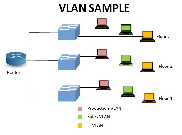
The above figure illustrates a simple VLAN configuration. A VLAN can extend to multiple physical locations, such as different floors, office campuses, etc. In the above figure, there are three VLANs- Production, Sales, and IT. The host connected to the IT VLAN on the first floor wouldn’t communicate with other hosts in rest two VLANs on the same floor, but would communicate with the hosts on the other floors joined in IT VLAN.
Similarly, all hosts of the Production VLAN will communicate with each other irrespective of their geographical location. The same applies to the third VLAN, i.e., the Sales VLAN. The traffic of one VLAN never enters another VLAN; hence, the VLAN also manages the traffic congestion apart from providing data security. With the implementation of VLAN, network administrators can logically manage the network without changing the physical topology.
We can use a third layer device like a router or a layer-3 switch to provide the inter VLAN communication, as shown in the diagram.
Advantage of the VLAN
VLAN provides efficient management of the network. It also adds an extra layer of security and flexibility to the system. The main advantages of VLAN are as under :
- Manage the size of the broadcast domain: By reducing the broadcast domain into smaller broadcast domains, it allows the administrator to combat traffic congestion.
- Provides additional security: The data with the VLAN tag delivers only to the hosts belonging to the same VLAN. It is extra security added to the network segment, as the traffic remains within the group of hosts. Without a VLAN, any user in the network-segment may have accessed the data, which may be not desirable to the organization.
- Logical grouping of devices: The administrator may logically group the devices irrespective of their geographical location. As we have already discussed, users from any floor, building, or campus may be grouped in the same VLAN and may access the data. On the other hand, users in the same location may not be able to access the data if they do not belong to the same VLAN. VLAN provides the flexibility to the administrator to customize the network.
- Inter VLAN traffic: The communication between VLANs is possible with the help of a Layer-3 device.
- Save the hardware resource: The same switch/set of switches can be used for multiple subnets reducing the overall requirement of hardware devices in the organization.
VLAN Parameters
VLAN is a Layer-2 architecture that follows the IEEE 802.1Q standard. The 802.1Q (commonly referred to as dot1q), is a standard that defines VLAN tagging. It adds a 4-byte field in the traditional Ethernet frame known as VLAN tagging.
The main parameters associated with VLAN are:
- VLAN Number (Vlan ID): It is the unique number that identifies a VLAN in a Network. It supports 4096 VLANs, with the permissible range 0-4095. VLAN 1 is the default VLAN, while other VLANs configured by the system administrator. The number 0 and 4095 are reserve for system use, 1 being the default VLAN, 2-1001 are configurable in Ethernet, 1002-1005 are reserve for FDDI and Token Ring. The range 1006-4094 is an extended range, with some added restrictions. VLAN 1 and 1002-1005, are already present in the switch you cannot delete them.
- VLAN Name: The text string to identify the VLAN with a significant name. It is an optional field VLAN can function without it. Though giving a meaningful name is a better practice.
- VLAN state: It can have either an active or suspended status. In the suspended state, VLAN traffic blocked in all switch ports. The default state of a VLAN is active.
Virtual LAN frame (IEEE 802.1Q)
As already discussed, VLAN tagging adds a 4-byte field to a traditional Ethernet frame known as VLAN tagging. The VLAN tag fits after the Source MAC address field in the frame. You can read my previous blog for the knowledge of Ethernet frames. The following diagram shows the VLAN tagging field added to an Ethernet frame.
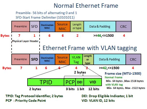
The 4 bytes of Vlan tagging consists of 2 bytes of Tag Protocol Identifier(TPID) and the remaining 2 bytes as tag Control Information(TCI). The TCI further splits into sub-fields- Priority Code Point (PCP)- 3 bits, Canonical Format indicator (CFI)/ Drop Eligible Indicator (DEI)- 1 bit, and VLAN ID (VID)- 12 bits. The minimum payload field permits 42-bytes, which was 46-bytes in a traditional Ethernet frame. Hence, the minimum frame size remains 64 bytes as in the ethernet frame; however, the maximum payload allowance is 1500 bytes. That means the maximum frame-length with a VLAN tag is 1522 bytes. In both cases, the Maximum Transmission Unit (MTU) is 1500 bytes.
Tag Protocol Identifier:
Its a two-byte field indicating the frame type. The default value for the IEEE802.1Q frame is 0x8100. The prefix ‘0x’ means its a Hex digit. Device vendors are independent to choose their TPID values. Users can change this value for interconnection between different devices.
Priority code point (PCP):
With the three available bits in this field, eight priority levels are possible from 0-7. It follows the 802.1p standard, larger the number, higher the priority. In the case of traffic congestion, the higher priority data clears first.
Drop eligible indicator (DEI):
The one-bit field with two options 0, or 1, also called the CFI (Canonical Format Indicator). The value is 0 for Ethernet by default. Useful for compatibility between Ethernet and Token Ring.
VLAN ID (Vlan ID):
The 12 bits may have 4096 combinations of VLAN ID from 0-4095, as discussed earlier in this article. This field is used to indicate the VLAN ID configured by the user.
Virtual LAN: Tagged and Untagged Frame
The switch-ports are of two types- tagged and untagged, also referred to as the access port and the trunk port, respectively. Simple hosts do not understand the tagged frame. A tagged unit consists of additional VLAN information apart from the regular ethernet headers. For the transmit and receive of those frames, a switch-port must have a configuration of a trunk port. By default, all the switch-ports are in access mode. All the ports will be a member of the default VLAN, i.e., VLAN 1.
All the hosts connect to the access port, while the switch-port connecting to other switch or router should be a trunk port for VLAN operation. To extend the multiple VLANs beyond one switch, over a common media, we need a trunk port.
The VLAN tagging or the frame tagging is a method to differentiate VLAN traffic over a trunk link. There are two main standards of VLAN tagging in Ethernet.
- IEEE 802.1Q
- ISL (Inter-Switch Link).
The former has already been explained in the above section, which adds 4 bytes of VLAN parameters in the traditional Ethernet frame. It is the open standard supported by all devices.
The ISL is the proprietary standard of Cisco, used in fast Ethernet and Gigabyte Ethernet links only. Its support is limited to the Cisco device. Rather than adding a field in the Ethernet frame like 802.1Q, it encapsulates the frame with an ISL header of 26 bytes. It also adds a 4-byte ISL frame check sequence (FCS) at the end of the frame. With the ISL, the frame length can go up to 1548 bytes with an additional 30 bytes ISL header and trailer upon the Ethernet frame of 1518 bytes.
Let us illustrate with examples, tagged, and untagged communication.
Access port to access port:
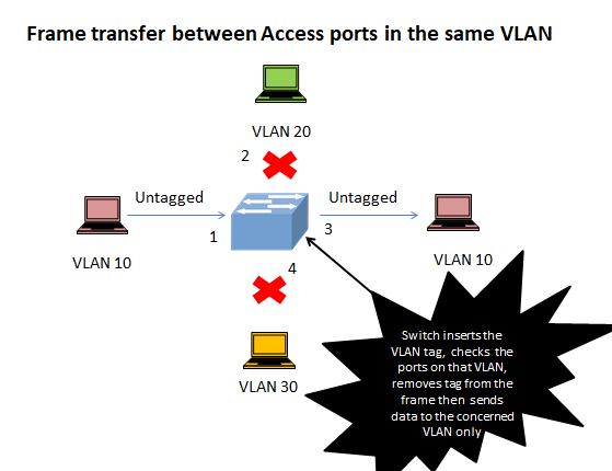
- A host on VLAN 10 sends an untagged frame to the switch to switch-port 1.
- The Network switch examines the VLAN membership of that switch-port and founds it to be in VLAN 10.
- The switch will add the VLAN tag to the frame. Now switch will decide to forward the frame to the access port 3.
- Switch now removes the VLAN tag and forwards the untagged frame to switch-port 3. The switch-ports 2 and 4 will not receive the frame as they are not in VLAN 10.
Access port to the trunk port:
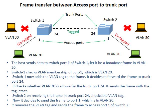
Refer to the above image for a clear understanding.
- The host sends data to switch-port 1 of Switch 1, let it be a broadcast frame in VLAN 20.
- Switch-1 checks VLAN membership of port-1, which is VLAN 20.
- Switch-1 now adds the VLAN tag to the frame and decides to forward the frame to trunk port 24.
- It checks whether VLAN 20 is allowed in the trunk port 24 then sends the frame with the tag intact.
- Switch 2 on receiving the frame in trunk port 24, checks the VLAN tag.
- Now it decides to send the frame to port 1, which is in VLAN 20.
- It removes the VLAN tag and sends the frame to access port 1 of Switch 2.
Static and dynamic Virtual LAN
Static VLAN: In this type, the network administrator first creates a VLAN, then adds the ports to that VLAN.
Suppose, one adds switch-port 1 to 10 in VLAN 10, those ports will permanently be assigned to VLAN 10 unless it is manually changed. Any host connecting to those switch-ports will be part of VLAN. It is based on the associated switch-port; hence, it is called a port-based VLAN.
Static VLANs are more secure than dynamic ones. It is easy to implement without requiring sophisticated hardware. Though the static VLAN is suitable for small enterprises, the management of VLANs is difficult in a broader scope.
Dynamic VLAN: In the dynamic VLAN, the switch reads the information of the host, like the IP address, and the MAC address and assigns the VLAN to the host automatically.
In the dynamic VLAN, there must be a switch configured as the VLAN Membership Policy Server. The administrator configures the VLAN database in the VMPS server. Generally, an advance and powerful device needed for VMPS as compared to static VLAN. When you connect any device to a switch-port, the device queries the VMPS database to get a membership of the VLAN. Depending upon the configuration and the host parameters, the VMPS server assigns a VLAN to the host. In dynamic VLAN, the host can move from one switch port to another, even to another switch, without changing the VLAN membership.
The more dig on the VLAN please go through the next blog, that covers the configuration part. Please drop a comment, suggestion, or query. Don’t forget to share the article if you feel it as informative.
Take a Quiz on this topic :