Types and functions of the Network Switch: Inroduction
Before we jumpstart to the configuration of the switch, let us first discuss the types and functions of the network switch in detail. This chapter describes the operation of the network switches and their varieties with the significance in the network.
As we have previously discussed, a network switch is a Layer 2 device that delivers frames according to the MAC address of a node. A layer-2 switch provides node-to-node delivery in the same network link. For the basic knowledge about network switch, please go through the chapter Network Hardware Devices.
I assume that you have gone through the chapter, so let’s discuss the types and functions of the network switch.
The term packet is used frequently in switching, although the practical ethernet switches deal with the ethernet frames, not with the upper layer datagrams like packets. It is the generic term in the context of the one of the switching technique, the packet switching.
Types and functions of the Network Switch: Circuit switching & Packet Switching.
Circuit switching establishes the physical circuit between the source and the destination. The connected channel remains intact until the completion of the full transmission. The correct example of circuit switching is the telephone system network. The latched circuit remains closed till the conversation is over in a telephone network.
The packet switching, on the other hand, split the entire message into manageable packets. Every packet contains the source and destination address, and it reaches the destination independently. The concerned layer ensures the correct delivery of them by sequencing, acknowledging, error-correcting, etc.
MAC Address
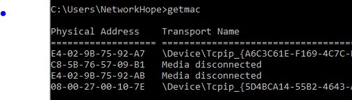
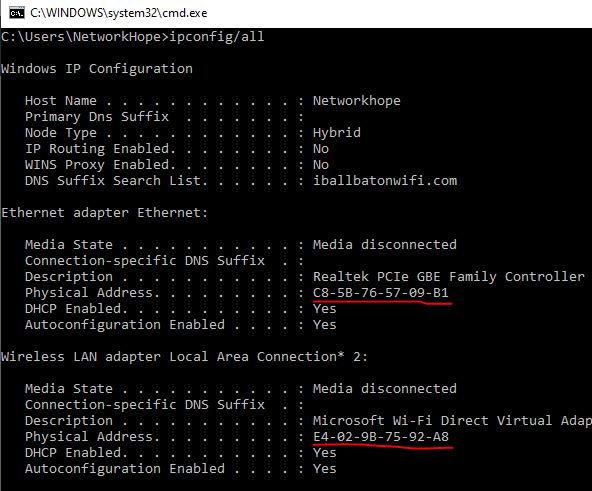
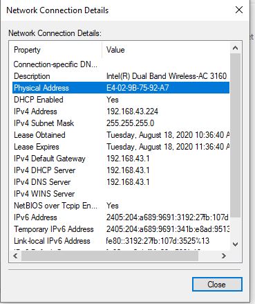
The physical address or the MAC address is the 48-bit address of any network interface assigned to the interface at the time of manufacturing. The 48 bits are written as 12 Hex digits in a group of two, separated by a hyphen, or sometimes a colon sign. It is also called the hardware address.
It consists of two parts:
The group of first 24 bits (3 octets) is the Organization Unique Identifier (OUI), and the remaining 24 bits are vendor-specific bits. The first three octets generally remain the same for a specific manufacturer like- HP, Dell, Cisco, Apple, etc. and the remaining three octets are different for each equipment. However, large manufacturing companies may have more than one OUI. You can check the MAC address of the interface from the command prompt using the “getmac” or “ipconfig/all” command. Alternatively, you can also check it from the Network properties of an interface by checking its status. You must connect the interface to the network for checking it from the GUI. The following picture illustrates the different methods of finding the MAC address.
Layer-2 forwarding is based on the MAC addresses of the source and destination hosts. The network switch forwards the frames to the destination by checking the destination MAC address.
Types and function of the network switch: Layer 2 forwarding methods
Though an Ethernet switch forwards the packet based on destination MAC address, different forwarding methods are there. Earlier, the layer 2 data packet was forwarded using a technique known as Store-and-Forward switching. Later in the 1990s, a new standard was evolved as the cut-through switching.
Store-and-Forward Switching
In the store-and-forward method, the switch takes the forwarding decision after receiving the whole frame and verifying the checksum for physical and data link error.
In store-and-forward, the switch stores the complete frame temporarily in buffer (RAM) memory, checks the Cyclic Redundancy Code (CRC) for any error. It computes the last 4 bytes of the datagram with its own Frame-Check-Sequence (FCS). The switch first ensures the frame as error-free and then forwards it.
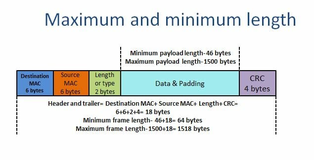
The store-and-forward method drops the frames in case of an error in them. It also discards the oversize and undersize frames. An ethernet frame smaller than 64 bytes is runt frame, and greater than 1518 bytes (payload 1500 bytes) is a giant frame. A store-and-forward switch discards both of them. However, the jumbo frames support the frame size up to 9000 bytes of payload.
Characteristics of store-and-forward switching
Error detection: As discussed above, the store-and-forward switching receives the complete frame before forwarding it to the destination MAC address. It examines the CRC at the end of the datagram and compares it with its own FCS. It drops the erroneous frames if detected any.
Buffering: The storing of the frame allows the switch to work efficiently with the different ethernet speeds. For example, a frame coming from a 10 Mbps link is to forward to a 1 Gbps link. The storing process of the entire datagram makes it easier to deliver it in such links.
Access control: Due to the storing process, it can examine the datagram to permit or deny access.
The obvious drawbacks of the store-and-forward switches are its high latency and demand for more processing and memory.
The following figures illustrate the Ethernet frame construction and its maximum and minimum limits.
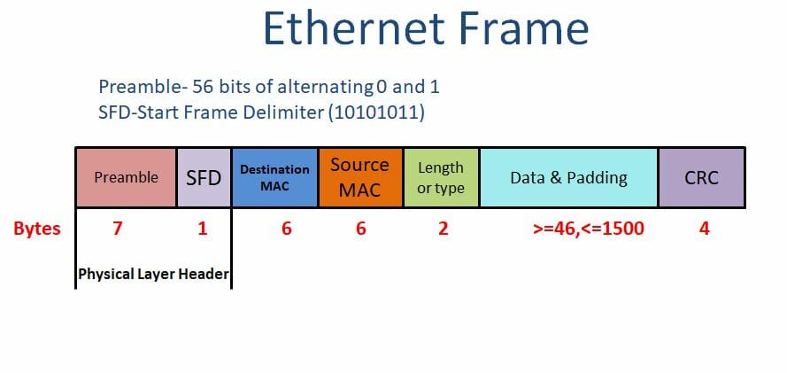
A brief idea of the Ethernet frame
As shown in the above figure, the Preamble and SFD fields add up in the Physical layer. Hence, they are not a part of the frame.
The preamble is the first field of the IEEE 802.3 frame consisting of 7 bytes or 56 bits. It has a binary stream of alternating 0s and 1s that alerts the receiving host and enables it to synchronize its input timing.
The Start Frame delimiter (SFD) is the second field of 1 byte consisting of a binary 10101011 signals the receiver about the beginning of the frame. The last two bits repeating 11 is the indication that the next data is the Destination MAC address.
Both of the fields are not counted for calculation of minimum and maximum frame length, as they are added in the physical layer.
The next two fields are destination MAC and the source MAC each of 48 bits or 6 bytes.
The Length or type field of 2 bytes used to specify the type of frame or the size of the data field in bytes. It may contain information regarding upper-layer protocol, like IPv4, IPv6, ARP, RARP, or the indication of VLAN tagging, etc. In some Ethernet frames, it is also used to indicate the size of the frame.
The data field contains the payload of varying sizes from 46 bytes to 1500 bytes.
The last field is CRC of 4 bytes containing the error detection information.
Cut-Through Switching
Unlike store-and-forward, the cut-through method starts the forwarding process as soon as it receives the destination MAC field of an incoming frame. As the CRC code is present at the end of the frame, a cut-through switch does not check for the physical or data-link errors. It leaves the job for the recipient.
It forwards the frame with physical or data-link errors to the next segment of the network. At the receiving end, the host itself checks for the error and discards the erroneous frames.
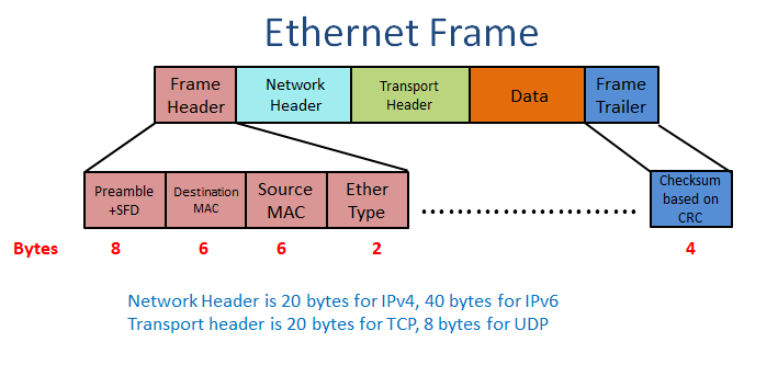
Theoretically, a cut-through switch takes the forwarding decision as soon as the DMAC field arrives, but in practice, it waits till several other bits are received. In the figure below, you can see that the payload contains the header of the upper layers along with the actual data. The diagram shows the network and transport layer headers.
Complexity in cut-through forwarding
Depending upon the data of the Ether type field, which contains the information about the upper-layer protocol, the switch may wait for the Network or transport layer headers. It examines the first 14 bytes (DMAC, SMAC, Ether Type) then determines whether to wait for the IP and TCP headers. In case of waiting for upper-layer headers to execute more sophisticated functions, it will wait till 54 bytes of data for a TCP packet in IPv4 routing. The forwarding decision can be taken after 54 bytes in case it has to take care of features like ACL.
A pure cut-through forwarding is only possible when the outgoing interface equals or exceeds in speed than the incoming interface. A cut-through switch has complex software and hardware architecture, as it needs to work like a store-and-forward switch on several occasions.
The condition when the input and output ports have speed mismatch or congestion in an egress (outgoing) interface may cause the cut-through Switch to hold the datagram partially or entirely.
Advantage of Cut-through switching
The main advantage of the cut-through switch is its forwarding time. Its latency is in the order of a few microseconds regardless of the frame size. They are more appropriate for high-performance computing applications.
Fragment free Switching
The third type of switching is fragment free switching. The fragment free switching is a kind of cut-through switching, where the switch holds the first 64 bytes of the frame. The fragment free switching is the trade-off between latency and error detection.
The concept behind it is that the datagram gets damaged by collision, which is generally shorter than the smallest frame size, i.e., 64 bytes. And the most errors and collision occurs during the first 64 bytes.
Also called as the runt-less switching, the fragment free switching discards the frames smaller than 64 bytes (runts). It buffers the first 64 bytes, updates the source MAC if needed, and forwards the packets to destination MAC.
As compared to Store-and-forward, it is faster, but not ensures the dropping of erroneous frames completely as store-and-forward does.
Different Types and functions of the Network Switch
Modular Switches
Modular switches are expandable switches where you can add the modules/cards for additional features. Those switches are flexible for add-on modules like Wireless, Network analysis, more interfaces, cooling, power supply, etc.
Fixed-Configuration Switches
They are not expandable and have a fixed number of ports. The fixed-configuration switches are further categorized as unmanaged, smart, and managed L2 and L3 types. The figure below illustrates the types of Ethernet and Network Switches.
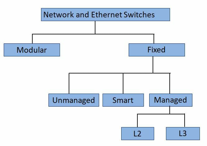
Unmanaged Switch
An unmanaged switch can directly be plug into a network without any initial configuration. It is suitable for small Networks like home, small office, or lab, etc. The unmanaged switches come in ready to use condition for basic Networking.
You can use these switches in networks when you require a few extra ports to connect devices. There are no security configurations you can add to them. They have some ethernet ports (generally 4, 8, 16, 24, or 48) and no console port at all. They come in all speed variants like Ethernet, Fast Ethernet, Gigabit Ethernet, or 10 Gbps.
Smart Switches
Smart switches the evolving category of switches. They offer some management features but are not as scalable as the managed switches. They are more affordable than the managed switch. You can use those switches in conjunction with the managed switches in large networks for edge implementation. The managed switches being the core switches.
The capability of the smart switches varies in different models. They can be configured for QoS, security, VLANs (Virtual LAN), some level of ACLs (Access Control List), etc.
Managed L2 and L3 switches
Managed switches are highly flexible, scalable, and powerful ones. The L2 Managed switches are generally used as aggregation and access switches in large networks and L3 as a core switch. The managed switch performs L2 switching as well as L3 IP routing, some of them are limited to L2 functions only. Remember that all managed switches are not an L3 switch, but all L3 switches are managed switches. Besides all the L2 switch functions, a Layer 3 switch also performs the inter VLAN routing function of Layer 3.
Features of a managed switch
- SNMP (Simple Network Management Protocol)-SNMP is for organizing and managing the status of managed devices for device management and monitoring.
- Spanning Tree Protocol-This protocol is used for creating redundant paths without loops. Also, see Types of STP.
- QoS- Quality of service to prioritize any specific link.
- VLAN- Create and manage VLANs, to split the single broadcast domain into multiple broadcast domains.
- Trunk tagging- Creating a trunk link and allow multiple VLANs.
- Port Mirroring- To allow all traffic to appear in a specific port for monitoring, recording, analyzing, etc..
- Port security- To secure the port with specific MAC address/ addresses.
- Bandwidth management
- Port aggregation for combining the speed of multiple ports.
- Redundancy – STP for redundant links, Port aggregation for redundant ports, etc.
Here I sum up the article Types and functions of the Network Switch. Share the article from the links given below, if you find it worth sharing. The upcoming posts will have more details of managed switched features and practical implementations. Stay connected to network hope, or you may follow our social links for updates.
Take a Quiz on this topic :